


1. Description, Specifications, and Part Numbers
1.1 Description
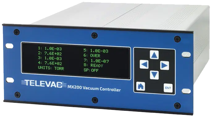
The MX200 is a modular, rack-mountable vacuum controller which controls up to ten vacuum sensors including cold cathode, convection, diaphragm, and thermocouple sensors. It also controls select capacitance diaphragm gauges (CDGs) from other manufacturers making it an extremely versatile solution for any vacuum measurement application. The capability of controlling a wide range of sensors allows the MX200 to provide a maximum vacuum measurement range of 1*10-11 Torr to 10,000 Torr.
The MX200 includes standard communications of USB, RS-232, and RS-485 standard. The user interface includes six capacitive touch controls and a high contrast green OLED display with a 180˚ viewing angle. All features are accessible through the front panel or through the digital communications. The digital communications also allow the MX200‘s operating system to be upgraded in the field.
The MX200 offers optional EthernetIP communications capability. EthernetIP is an increasingly popular industrial network communication standard compatible with Rockwell Automation Allen-Bradley programmable logic controllers (PLCs) and PCs. The EthernetIP version of the Televac® MX200 Vacuum Controller supports EthernetIP communications, allowing the users to interface directly with supported PLCs and PCs, including the ability to acquire vacuum data and adjust settings from a convenient, remote location without complicated conversion tools.
The PROFINET version of the MX200 Vacuum Controller enhances connectivity in industrial environments by supporting PROFINET communication standards. This allows seamless integration with PROFINET-enabled devices, such as Siemens SIMATIC PLCs, enabling users to monitor and control vacuum processes in real time through a unified network. With this upgrade, the MX200 provides enhanced data acquisition capabilities and supports advanced automation protocols, making it ideal for modern manufacturing and process control applications that demand reliable, high-speed communication.
The Televac® brand of The Fredericks Company was created in 1935 and is an industry leader in vacuum measurement technology. Our team of engineers and application specialists deliver broad practical knowledge and experience across a wide range of markets and application areas. In keeping with the company’s history of outstanding customer support, Televac® provides the insight and guidance needed to take design concepts to reality in a cost-effective manner. For more information, visit our website at www.frederickscompany.com.
1.2 MX200 Specifications
| Operating Range | 1*10-11 Torr to 10,000 Torr |
| Communications | RS-232/RS-485/USB (standard) EthernetIP/USB PROFINET/USB |
| Analog Output | 0 V DC to 10 V DC (1 per sensor) |
| Analog Output Resolution | 16 bits |
| Programmable Set Points | 4 per module, 8 maximum |
| Set Point Type | Relay |
| Supply Voltage | 115/230 V AC (2/1 A), 50/60 Hz |
| Maximum Power | 230 W |
| Calibration Medium | Dry air or nitrogen |
| Operating Temperature | 0 °C to 50 °C |
| Storage Temperature | -20 °C to 70 °C |
| Display Readable Distance | Up to 5 m (16 ft) |
| Maximum Sensors Controlled | 10 |
| Maximum Sensors Displayed | 8 |
1.3 MX200 Part Numbers
| Description | Part Numbers |
| MX200 Vacuum Controller Base Unit (RS-232/RS-485/USB) | 2-7900-034 |
| MX200 Vacuum Controller Base Unit (EthernetIP/USB) | 2-7900-037 |
| MX200 Vacuum Controller Base Unit (PROFINET/USB) | 2-7900-038 |
| Quad Relay Module | 2-6200-411 |
| RS-232/RS-485/USB Communications Module | 2-6200-213 |
| EthernetIP/USB Communications Module | 2-6200-314 |
| PROFINET/USB Communications Module | 2-6200-315 |
| 1E Piezo Diaphragm Module | 2-6200-220 |
| 1F Piezo Diaphragm Module | 2-6200-244 |
| 2A Dual Thermocouple Module | 2-6200-486 |
| 4A Dual Convection Module | 2-6200-415 |
| 7B Penning Magnetron Cold Cathode Module | 2-6200-227 |
| 7E/7F/7FC/7FCS Double Inverted Magnetron Cold Cathode Module | 2-6200-285 |
| Dual Capacitance Diaphragm Module (24 V DC) | 2-6200-451 |
| Dual Capacitance Diaphragm Module (15 V DC) | 2-6200-452 |
2. Safety Information
2.1 General Safety Information
- All maintenance and repairs must be completed by a trained technician. There are no user serviceable parts inside the unit and no parts should be substituted or modified without approval from the factory. Refer to the factory for all information related to maintenance and repairs.
- Always power down and disconnect power from the unit before attempting to perform service. Use the power cord as the main disconnect to remove all power from the unit.
- This unit can be used with 110 V AC or 220 V AC power. There is a switch on the back of the unit to change between the two settings. Failure to use a correct power source may cause damage to the unit. See Section 5 for more information.
- Hazardous high voltages (2 kV to 4 kV) are present when any cold cathode modules are installed. This includes the 7B/E/F/FC/FCS modules.
- Strong magnetic fields are present near cold cathode sensors.
- Take proper precautions to avoid hazardous overpressure conditions.
- Televac® and The Fredericks Company are not liable for any direct or indirect damages that result from the use of the MX200 or its peripherals.
3. Quick Start Guide
3.1 Check what you’ve received
Compare what you’ve received to your purchase order. Note that while listed as separate items, the modules for the MX200 are shipped pre-installed in the MX200 base unit from the factory for your convenience.
3.2 Safety Instructions
Review all safety instructions outlined in Section 2.
3.3 Check the MX200 Power Supply Switch
Ensure that the MX200 power supply switch is set to the correct voltage. The options are 110 V AC and 220 V AC. Selecting the incorrect voltage will cause damage to the unit. See Section 5 for more information.
3.4 Connect Power
Connect the power cord provided with the MX200 to a suitable power supply.
3.5 Turn on the MX200!
This is the moment you’ve been waiting for. Flip the power switch on the power supply on the back of the MX200 (beneath where the power cord is connected). The loading screen should now be displayed.
3.6 Check the Measurement Screen
After a few seconds, the MX200 will complete its startup sequence and load the measurement screen. With no cables or sensors connected, all displayed channels should read OVER, READY, or OFF.
3.7 Power down the MX200 and connect peripherals
Once you’ve confirmed that the MX200 is functional, power it down. Connect all sensors using sensor cables, and connect any analog output, set point, or digital communications cables as necessary. Be sure to follow all safety precautions associated with these items and your system.
3.8 Enjoy your MX200
We love the MX200 and we know you will too. Please don’t hesitate to contact us with any questions or comments!
4. Physical Characteristics
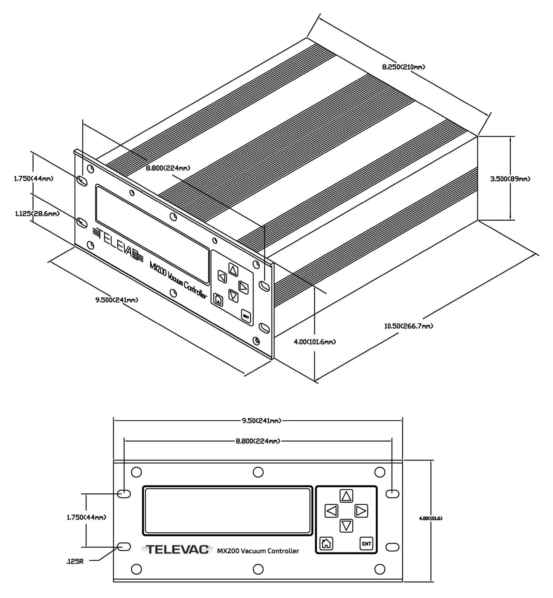
4.1 Enclosure
The MX200 has an aluminum enclosure. The dimensions are the same as the existing MM200 and are shown below:
4.2 Mounting
Free Standing
The MX200 can be used as a free standing unit, four rubber feet are shipped with each unit. When used as a free standing unit it must be secured to the mounting surface.
Panel Mounted
A panel cutout of 89 mm x 210 mm (3.50” x 8.25”) is required for the unit.
Rack Mounted
The mounting hole vertical spacing is 44 mm (1.175”).
4.3 Labeling
The MX200 is labeled with a CE/UL compliance label, a calibration label, and a serial number label. All units are given a unique serial number before being shipped by Televac®.
5. Electrical Requirements
5.1 Power
| Supply Voltage | 110/220 V AC ±10%, 50/60 Hz |
| Supply Current | 2A @ 115 V AC, 1A @ 230 V AC |
| Power | 230 W maximum |
| Power Connection | Power cord (IEC 60320 C-13) |
5.2 Selecting the Supply Voltage
There is a switch located above the power supply connection on the back of the unit. Verify that this switch is in the correct position before connecting power to the unit.
5.3 Electrostatic Discharge Sensitivity
The MX200 contains ESD-sensitive components but is designed to withstand ±2 kV discharges using the human body model.
6. Environmental Specifications
6.1 Temperature
| Operating Temperature | 0° to +50 °C |
| Storage Temperature | -20° to +70 °C |
6.2 Humidity
| Operating Humidity | 10% to 90% non-condensing relative humidity |
| Storage Humidity | 10% to 90% non-condensing relative humidity |
6.3 Altitude
| Operating Altitude | Sea level to 2,000 m (6,500 feet) |
| Storage Altitude | Sea level to 2,000 m (6,500 feet) |
7. User Interface
7.1 Display
| Type | Green OLED |
| Resolution | 256 x 64 pixels |
| Viewing Area | 35 mm x 136 mm (1.38″ x 5.35″) |
| Viewing Distance | Up to 5 m (15 ft), dependent on number of channels displayed |
7.2 Touch Controls
| Type | Capacitive switch |
| ↑ Button | Move the cursor up or adjust a value up |
| → Button | Move into menu at cursor or move right one digit |
| ← Button | Go back one menu or move left one digit |
| ↓ Button | Move the cursor down or adjust a value down |
| ENT Button | Save a new setting or value |
| ⌂ (Home) Button | Return to the main menu |
Capacitive touch controls do not provide any tactile feedback, so audible feedback is generated when a control is pressed.
7.3 MX200 Menu Structure
- Measurements
- Measurement Screen
- Channel Setup
- Channel 1 … Channel 10
- Display
- Gas
- Resolution
- Analog Output
- Restore Defaults
- Calibration
- Channel 1 … Channel 10
- Sensor dependent
- Channel 1 … Channel 10
- Global Setup
- Measurement Screen
- Channel 1 … Channel 10
- Units
- Pascal
- Torr
- mbar
- Torr Dec
- mT | Torr
- Gas
- Channel 1 … Channel 10
- Communications
- RS-232/EthernetIP/PROFINET
- Baud Rate
- RS-485 (2-7900-034 ONLY)
- Address
- Baud Rate
- USB
- Baud Rate
- RS-232/EthernetIP/PROFINET
- Cold Cathode
- Mode
- Even Status
- Odd Status
- Switch Point
- Restore All Defaults
- Measurement Screen
- Set Points
- Set Point 1 … Set Point 8
- On
- Off
- Channel
- Version Information
8. Measurement Screen
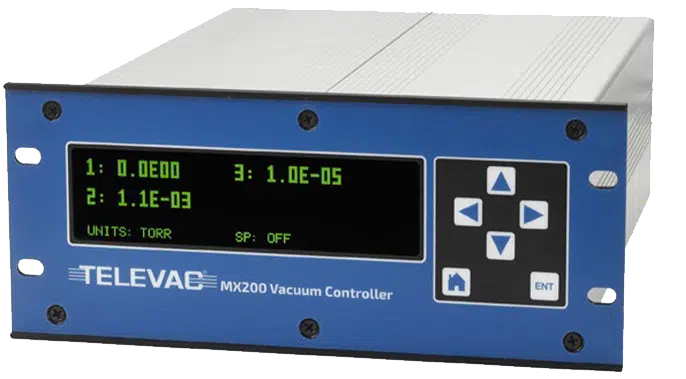
8.1 Description
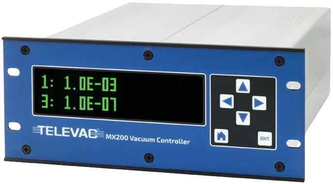
The measurement screen displays the output from 0 channels up to 8 channels and scales the text size accordingly. In addition to measurements, it also simultaneously displays the units of measurement (Torr, mbar, Pascal, Torr decimal, or mTorr/Torr, note that mTorr is equivalent to microns) and the active set points. The measurement screen comes up automatically when the unit is powered. To exit the measurement screen and enter other menus, press the left or home button.
Auto-scaling measurement screen examples:
8.2 Selecting Channels to Display
To select which channels to display, press the home button then navigate to:
Global Setup > Measurement Screen
This will show a list of all channels. The display status of all connected channels is shown as “yes” or “no”. To switch a channel between yes and no, move the cursor to the desired channel using the up and down buttons, then press the ENT button. If more than 6 channels are connected, continue scrolling down to view additional channels. Turning a channel display on or off can also be accomplished through digital communications. Refer to Section 9 for more information.
Another way to select which channels to display is to press the home button then navigate into:
Channel Setup > Channel X
Using the up and down buttons, scroll the cursor to the “Display: Yes/No” row and press the ENT button to change the current setting. Pressing the left or home button without pressing ENT will exit the menu without saving any changes.
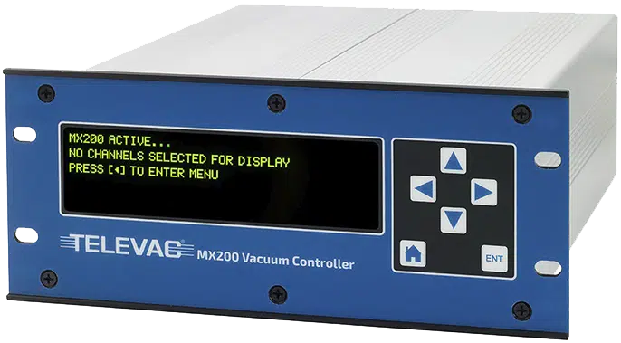
8.3 Zero Channel Display
This feature is designed for applications where the MX200 output is connected to another controller through the 0 to 10 V DC analog outputs of each sensor. In this situation, due to conversion and latency, there can be a mismatch between the measurements on the front panel of the MX200 and the other controller. Turning off the front panel measurements removes any concerns related to this mismatch. When displaying zero channels, the measurement screen will appear as follows:
8.4 Units of Measurement
The MX200 supports units of Torr, mbar, Pascal, Torr decimal, and mTorr/Torr (mTorr is equivalent to microns). Torr decimal displays the output in decimal notation instead of scientific notation. mTorr/Torr switches the units of measurement to mTorr (microns) between 1 mTorr and 999 mTorr for rough vacuum sensors. Note that Torr decimal and mTorr/Torr notation only apply to rough vacuum sensors such as the Televac® 2A and 4A. To change the units of measurement, press the home button then navigate into:
Global Setup > Units
The currently selected units of measurement are displayed at the top of the list. Scroll to a different option and press ENT to change the units. Press the left or home button to exit the menu. Pressing the left or home button without first pressing ENT will exit the menu without saving a new setting.
8.5 Resolution of Measurement
Channel measurements can be set to high or standard resolution. More details about these options are described below for different measurement units. The resolution for a specific channel can be changed by pressing the home button then navigating to:
Channel Setup > Channel X > Resolution Std/High
The currently selected resolution is displayed at the top of the list. Scroll to a different option and press ENT to change the resolution. Press the left or home button to exit the menu. Pressing the left or home button without first pressing ENT will exit the menu without saving a new setting.
Resolution when the units are set to Torr, mbar, or Pascal:
| Range (Torr) | High Resolution | Standard Resolution |
| Full Range | 3 significant digits | 2 significant digits |
Resolution when the units are set to Torr decimal:
| Range (Torr decimal) | Standard or High Resolution |
| 100 to 1000 | 1 Torr |
| 10 to 100 | 0.1 Torr |
| 1 to 10 | 0.01 Torr |
| 0.001 to 1 | 0.001 Torr |
Resolution when the units are set to mTorr/Torr (mTorr is equivalent to microns):
| Range (mTorr) | Standard or High Resolution |
| 1 to 999 | 1 mTorr |
8.6 Sampling Rate
The readings for all vacuum sensors connected to the MX200 are sampled at a minimum rate of 100 Hz.
8.7 Leak Rate
To enter the leak rate mode, press the up arrow then ENT to start the leak rate calculation and the down arrow then ENT to stop the calculation. This can only be done while in the measurement screen. The leak rate is displayed in mTorr (mTorr is equivalent to microns) regardless of the settings for units of measurement, and is only calculated for channel 1. The channel 1 measurement will rotate between the channel 1 measurement and the leak rate, with the measurement displaying for 2 seconds and the leak rate displaying for 1 second.
After entering the leak rate mode, the unit requires 15 seconds to make the first calculation. During this time the display will show “LR” until the leak rate is calculated. If the leak rate calculation has already been started through digital communications, it must be stopped through the front panel (down arrow then ENT button), or through digital communications before it can be started again. See Section 9 for more information.
There is a timeout for the leak rate calculation after 9 hours.
9. Serial Communications
9.1 READ THIS FIRST – Important Note Information on Establishing Communication
NOTE THAT COMMANDS THAT SAVE OR CHANGE VALUES STORED IN MEMORY CAN ONLY BE USED WHEN THE MX200 IS IN THE MEASUREMENT SCREEN. If the MX200 is not in the measurement screen when a save or change command is used, an error code of 0N0000 will be returned.
All other commands can be accessed from any a screen. ALSO NOTE THAT ONLY THE SELECTED MODE OF COMMUNICATION WILL BE FUNCTIONAL. See Section 9.3 for methods of switching the communication modes or viewing the current mode.
9.2 Communication Modules
The MX200 comes with a standard communication module that includes USB, RS-232, and RS-485 interfaces. For customers seeking EthernetIP or PROFINET compatibility, we also offer dedicated communication modules for either EthernetIP or PROFINET as an alternative option.
9.3 Switching Communication Modes or Viewing the Current Mode
The MX200 can be switched between communication modes or the current mode can be viewed by pressing the home button and navigating to:
Global Setup > Communications > Interface
The current mode can then be viewed or a new mode can be selected by pressing ENT on the desired mode. Only one mode of communication can be active at any given time.
9.4 RS-232 Interface Description
| Interface | D-sub 9 pin female port on communications module |
| Baud Rate | 9600, 14400, 19200, 38400, 57600, or 115200 (default) |
| Data Format | 8 data bits, 0 parity bits, 1 stop bit |
| Error Detection | None |
| Transfer Distance | 10 m (30 ft) |
Pin Diagram
| Pin | Signal Description |
| 1 | Ground |
| 2 | RS-232 TX |
| 3 | RS-232 RX |
| 4 | No Connection |
| 5 | Ground |
| 6 | No Connection |
| 7 | Ground |
| 8 | No Connection |
| 9 | Ground |
9.5 RS-485 Interface Description
| Interface | 3 position screw terminal block on communication module |
| Addresses | 00 to 99 (decimal), default value is 00 |
| Baud Rate | 9600, 19200, 38400, 57600, or 115200 (default) |
| Data Format | 8 data bits, 0 parity bits, 1 stop bit |
| Error Detection | None |
| Transfer Distance | 300 m (1000 ft) |
| Maximum Nodes on Bus | 16 |
3 Positioin Screw Terminal Block Pin Diagram
| Pin | Signal Description |
| 1 | RS-485 B |
| 2 | RS-485 A |
| 3 | Ground |
9.6 USB Interface Description
| Interface | USB type B receptacle on communications module |
| Type | USB 2.0 |
| Class | USB communications device class (USB CDC) |
| Baud Rates | 9600, 19200, 38400, 57600, and 115200 |
9.7 Connecting to a PC and Establishing Communication
Televac® suggests the use of USB communications when connecting the MX200 to a PC. Televac® also suggests the use of the free serial communications software such as the Fredericks Company Web Serial Terminal, Tera Term, or PuTTy to send and receive commands from the unit. Detailed instructions for establishing communication between a PC and any of our products can be found in Televac® Application Note 3008: MX200 PC Interfacing Communications.
9.8 Full List of Commands
| Command | Sample Output | Description |
| R1<cr> | XX<cr><lf> | Outputs units setting XX: PA=Pascal, TR=Torr, MB=mBar, TD=Torr decimal, MT=mTorr/Torr |
| W1XX<cr> | XX<cr><lf> | Set units to XX: PA=Pascal, TR=Torr, MB=mBar, TD=Torr decimal, MT=mTorr/Torr |
| S1XX<cr> | ppsee<cr><lf> | Vacuum reading for channel XX is ppsee |
| S1<cr> | XX=ppsee … XX=ppsee<cr><lf> | Output ppsee readings for every channel XX |
| S2<cr> | NNNNNN<cr><lf> | Logic firmware version |
| S3<cr> | NNNNNN<cr><lf> | Display firmware version |
| S4<cr> | XX=YY … XX=YY<cr><lf> | Output channel sensor types: XX = channel number, YY = sensor type |
| S5<cr> | XX=YY … XX=YY<cr><lf> | Output set point XX status YY (ON=on, OF=off, 00=no set point connected) |
| S6<cr> | Televac … <cr><lf> | Output all setup information |
| RC1XX<cr> | Baa<cr><lf> | Output first calibration point for channel XX |
| RC2XX<cr> | Baa<cr><lf> | Output second calibration point for channel XX |
| RC3XX<cr> | Baa<cr><lf> | Output third calibration point for channel XX, return error if point doesn’t exist |
| RC4XX<cr> | Baa<cr><lf> | Output fourth calibration point for channel XX, return error if point doesn’t exist |
| WC1XXBaa<cr> | PPSEE<cr><lf> | Set first calibration point for channel XX |
| WC2XXBaa<cr> | PPSEE<cr><lf> | Set second calibration point for channel XX |
| WC3XXBaa<cr> | PPSEE<cr><lf> | Set third calibration point for channel XX, return error if point doesn’t exist |
| WC4XXBaa<cr> | PPSEE<cr><lf> | Set fourth calibration point for channel XX, return error if point doesn’t exist |
| R2<cr> | 01 02 03 04 05 … <cr><lf> | Outputs channel numbers connected to the MX200 |
| R3XX<cr> | HI<cr> or LO<cr><lf> | Outputs HI/LO resolution for channel XX |
| W3XX<cr> | HI<cr> or LO<cr><lf> | Toggle HI/LO resolution for channel XX |
| R4<cr> | 01 02 03 04 05 … <cr><lf> | Outputs channel numbers set to display on measurement screen |
| W4XX<cr> | ON<cr> or OF<cr><lf> | Adds or removes channel XX from measurement screen |
| R5XX<cr> | FbaaBAA<cr><lf> | Output analog output format, high and low values |
| W5XXF<cr> | F<cr><lf> | Set channel XX analog output format to linear-by-decade (lin/dec=3, lin/dec 7E=4) |
| W5XX1baa<cr> | Fbaa<cr><lf> | Set channel XX analog output format to linear: baa=high value |
| W5XX2baaBAA<cr> | FbaaBAA<cr><lf> | Set channel XX analog output format to linear: baa=high value, BAA=low value |
| R6XX<cr> | GG<cr><lf> | Output gas setting for channel XX |
| W6XXGG<cr> | GG<cr><lf> | Set channel XX to gas type to GG |
| R7Y<cr> | ppseePPSEEZZ<cr><lf> | Output relay Y on = ppsee, relay Y off = PPSEE, and channel ZZ assigned to relay Y |
| W7YppseePPSEEZZ<cr> | ppseePPSEE<cr><lf> | Set relay Y on to ppsee, relay Y off to PPSEE, and relay Y to channel ZZ |
| R8<cr> | A<cr><lf> | Outputs the cold cathode mode, A (auto = 1, self = 2) |
| W8A<cr> | A<cr><lf> | Sets the cold cathode mode, A (auto = 1, self = 2) |
| R9<cr> | BB<cr><lf> | Returns the cold cathode switch point value, BB (01 to 50) |
| W9BB<cr> | BB<cr><lf> | Sets the cold cathode switch point value, BB (01 to 50) |
| R10<cr> | CD<cr><lf> | Returns the cold cathode status odd and even (on/off) C-odd, D-even (0 = off, 1 = on) |
| W10CD<cr> | CD<cr><lf> | Sets the cold cathode status odd and even (on/off) C-odd, D-even (0 = off, 1 = on) |
| C1TTTT<cr> | TTTT<cr><lf> | Set baud rate to TTTT |
| C2EE<cr> | EE<cr><lf> | Set address to EE (00 to 99), RS-485 only |
| C4N<cr> | N<cr><lf> | Change I/O to N (RS-232=1, RS-485=2, USB=3) |
| C1<cr> | TTTT<cr><lf> | Output baud rate setting |
| C2<cr> | EE<cr><lf> | Output address for RS-485 |
| C4<cr> | N<cr><lf> | Output communications type (RS-232=1, RS-485=2, USB=3) |
| HM<cr> | M<cr><lf> | Return to the measurement screen |
| RLR<cr> | SXXX<cr> | Output the leak rate calculation or channel 1 in mTorr (S=sign, XXX=-999 to 999) |
| WLRX<cr> | X<cr><lf> | Turn on or off leak rate calculation for channel 1 (0=off, 1=on) |
| WD_1XX<cr> | XX<cr><lf> | Restore channel setup defaults for channel XX |
| WD_7X<cr> | X<cr><lf> | Restore set point relay defaults for set point X |
| WD_CXX<cr> | XX<cr><lf> | Restore calibration defaults for channel XX |
| WD_G<cr> | D<cr><lf> | Restore defaults for global setup |
| SN<cr> | NNNNNN<cr><lf> | Returns the six digit serial number of the unit, with values from 000000 to 999999 |
| PG_LGC<cr> | Bootloader … <cr><lf> | Enters the bootloader for the logic firmware |
| PG_DSP<cr> | Bootloader … <cr><lf> | Enters the bootloader for the display firmware |
9.9 Notes on Commands
All commands are appended with a carriage return(<cr>, ASCII 0x0D) and all responses are appended with a carriage return and line feed (<cr><lf>, ASCII 0x0D 0x0A).
For RS-485 communications, all commands are prepended with *AA where AA is the address of the unit. For example, the R1<cr> RS-485 command for a unit with address 00 would be *00R1<cr>.
Digital vacuum measurement values output through communications are updated at a rate of 100 Hz or faster.
9.10 Detailed Command Descriptions
R1<cr>
This command is used to read the current setting for the measurement units. The units supported by the MX200 are Torr, millibar, Pascal, Torr decimal, and mTorr/Torr (mTorr is equivalent to microns). After sending this command, the returned value will indicate the current setting for the units of measurement.
| Response | Description |
| PA | Units are set to Pascal (scientific) |
| TR | Units are set to Torr (scientific) |
| MB | Units are set to millibar (scientific) |
| TD | Units are set to Torr decimal (low vacuum sensors only) |
| MT | Units are set to mTorr/Torr (low vacuum sensors only) |
Example:
[USER TX] R1<cr>
[USER RX] TR<cr><lf>
W1XX<cr>
This command is used to change the current setting for the units of measurement. The units supported by the MX200 are Torr, millibar, Pascal, Torr decimal, and mTorr/Torr (mTorr is equivalent to microns). After sending this command, the returned value will indicate the new setting for the units of measurement.
| Command | Description |
| W1PA | Set units to Pascal (scientific) |
| W1TR | Set units to Torr (scientific) |
| W1MB | Set units to millibar (scientific) |
| W1TD | Set units to Torr decimal (low vacuum sensors only) |
| W1MT | Set units to mTorr/Torr (low vacuum sensors only) |
| Response | Description |
| PA | Units are now set to Pascal (scientific) |
| TR | Units are now set to Torr (scientific) |
| MB | Units are now set to millibar (scientific) |
| TD | Units are now set to Torr decimal (low vacuum sensors only) |
| MT | Units are now set to mTorr/Torr (low vacuum sensors only) |
Example:
[USER TX] W1TR<cr>
[USER RX] TR<cr><lf>
S1XX<cr>
This command is used to read the vacuum reading for a single channel XX. The channel number can be from 01 to 10, and is dependent on the configuration of your MX200. After sending this command the response is the vacuum reading from channel XX in the format of ppsee (p.p * 10see):
| Command | Description |
| W1XX | Read vacuum reading for channel XX (01 to 10) |
| Response | Description |
| pp | Mantissa of the reading (1.0 to 9.9) |
| s | Sign of the exponent (0 = negative, 1 = positive) |
| ee | Exponent (00 to 11) |
Example of reading the value from channel 1 which has a reading of 1.0 x 10⁻³:
[USER TX] S101<cr>
[USER RX] 10003<cr><lf>
If high resolution is enabled, the output will be pppsee (p.pp * 10see).
S1<cr>
This command outputs the vacuum readings for all channels connected to the MX200 in a string “01=ppsee 02=ppsee … 10=ppsee<cr>”, delimited with spaces. The format of the vacuum readings is ppsee (p.p * 10see).
| Response | Description |
| pp | Mantissa of the reading (1.0 to 9.9) |
| s | Sign of the exponent (0 = negative, 1 = positive) |
| ee | Exponent (00 to 11) |
Example output with an MX200 configuration with channels 1, 2, and 3 connected with readings of 1.0 x 10⁻³, 7.6 x 10², and 5.1 x 10⁻⁵ respectively:
[USER TX] S1<cr>
[USER RX] 1=10003 2=76102 3=51005<cr><lf>
If high resolution is enabled, the output will be pppsee (p.pp * 10see).
S2<cr>
This command outputs the logic firmware version. The returned value is 6 digits where each digit is a number from 0 to 9.
Example where the logic version is 160322:
[USER TX] S2<cr>
[USER RX] 160322<cr><lf>
S3<cr>
This command outputs the display firmware version. The returned value is 6 digits where each digit is a number from 0 to 9.
Example where the display version is 160322:
[USER TX] S3<cr>
[USER RX] 160322<cr><lf>
S4<cr>
This command outputs the sensor type associated with each channel in a string with the format “01=XX 02=XX … 10=XX<cr>”, delimited with spaces. XX is the sensor type and a table of possible responses is below.
| Response | Sensor Type |
| 1E | 1E piezo diaphragm |
| 1F | 1F piezo diaphragm |
| 2A | 2A/Mini/NASA thermocouple |
| 4A | 4A convection |
| 7B | 7B Penning cold cathode |
| 7F | 7E/7F/7FC/7FCS double inverted magnetron cold cathode |
| 5A | 1000 Torr capacitance diaphragm |
| 5B | 100 Torr capacitance diaphragm |
| 5C | 10 Torr capacitance diaphragm |
| 5D | 1 Torr capacitance diaphragm |
| 5E | 0.1 Torr capacitance diaphragm |
S5<cr>
This command outputs the set point relay status. The return value is a string with the format “01=XX 02=XX … 08=XX<cr>”, delimited with spaces, where XX is the status of the set point relay. A table of possible responses is below.
| Response | Description |
| ON | Relay is on |
| OF | Relay is off |
| 00 | No set point relay connected |
S6<cr>
This command outputs information on all settings for the MX200. The response is a multi-line string with the format below. Note that this command is not meant for real time data acquisition and you should use at least 1 second delays between sending the command:
| Line # | String |
| Line 1 | Televac – The Fredericks Company, www.frederickscompany.com<cr><lf> |
| Line 2 | MX200, Serial Number NNNNNN, Logic NNNNNN, Display NNNNNN<cr><lf> |
| Line 3 | Channel Sensor Type<cr><lf> |
| Line 4 | 01=XX 02=XX … 10=XX<cr><lf> |
| Line 5 | Channels Set to Display<cr><lf> |
| Line 6 | XX YY … ZZ<cr><lf> |
| Line 7 | Channel Gas Type<cr><lf> |
| Line 8 | 01=XX 02=XX … 10=XX<cr><lf> |
| Line 9 | Channel Resolution<cr><lf> |
| Line 10 | 01=XX 02=XX … 10=XX<cr><lf> |
| Line 11 | Channel Analog Format<cr><lf> |
| Line 12 | 01=X 02=X … 10=X<cr><lf> |
| Line 13 | Channel Analog High<cr><lf> |
| Line 14 | 01=baa 02=baa … 10=baa<cr><lf> |
| Line 15 | Channel Analog Low<cr><lf> |
| Line 16 | 01=baa 02=baa … 10=baa<cr><lf> |
| Line 17 | Set Point Relay Channel Associations<cr><lf> |
| Line 18 | 01=XX 02=XX 03=XX<cr><lf> |
| Line 19 | Set Point Relay Low Values<cr><lf> |
| Line 20 | 01=ppsee 02=ppsee … 08=ppsee<cr><lf> |
| Line 21 | Set Point Relay High Values<cr><lf> |
| Line 22 | 01=ppsee 02=ppsee … 08=ppsee<cr><lf> |
| Line 23 | Cold Cathode Mode: YYYY<cr><lf> |
| Line 24 | Cold Cathode Control Channels<cr><lf> |
| Line 25 | 01=XX 02=XX … 10=XX<cr><lf> |
| Line 26 | Calibration Values<cr><lf> |
| Line 27 | 01 1=YYY 2=YYY 3=YYY 4=YYY<cr><lf> |
| Line 28 | 02 1=YYY 2=YYY 3=YYY 4=YYY<cr><lf> |
| Line 29 | 03 1=YYY 2=YYY 3=YYY 4=YYY<cr><lf> |
| Line 30 | 04 1=YYY 2=YYY 3=YYY 4=YYY<cr><lf> |
| Line 31 | 05 1=YYY 2=YYY 3=YYY 4=YYY<cr><lf> |
| Line 32 | 06 1=YYY 2=YYY 3=YYY 4=YYY<cr><lf> |
| Line 33 | 07 1=YYY 2=YYY 3=YYY 4=YYY<cr><lf> |
| Line 34 | 08 1=YYY 2=YYY 3=YYY 4=YYY<cr><lf> |
| Line 35 | 09 1=YYY 2=YYY 3=YYY 4=YYY<cr><lf> |
| Line 36 | 10 1=YYY 2=YYY 3=YYY 4=YYY<cr><lf> |
RC1XX<cr>
This command returns the first adjustment point for channel XX (01 to 10). The return value has the format Baa where B is the sign (0 for negative and 1 for positive) and aa is a numeric value for the calibration point from 00 to 99.
Example reading a calibration value of -25 from channel 1:
[USER TX] RC101<cr>
[USER RX] 025<cr>
RC2XX<cr>
This command returns the second adjustment point for channel XX (01 to 10). The return value has the format Baa where B is the sign (0 for negative and 1 for positive) and aa is a numeric value for the calibration point from 00 to 99.
Example reading a calibration value of -25 from channel 1:
[USER TX] RC201<cr>
[USER RX] 025<cr><lf>
RC3XX<cr>
This command returns the third adjustment point for channel XX (01 to 10). The return value has the format Baa where B is the sign (0 for negative and 1 for positive) and aa is a numeric value for the calibration point from 00 to 99. Note that if no third adjustment point exists for the sensor connected to the chosen channel, an error will be returned.
Example reading a calibration value of -25 from channel 1:
[USER TX] RC301<cr>
[USER RX] 025<cr><lf>
RC4XX<cr>
This command returns the fourth adjustment point for channel XX (01 to 10). The return value has the format Baa where B is the sign (0 for negative and 1 for positive) and aa is a numeric value for the calibration point from 00 to 99. Note that if no fourth adjustment point exists for the sensor connected to the chosen channel, an error will be returned.
Example reading a calibration value of -25 from channel 1:
[USER TX] RC401<cr>
[USER RX] 025<cr><lf>
WC1XXBaa<cr>
WARNING – IF THE USER ADJUSTS THE CALIBRATION VALUES ON AN ISO 17025 ACCREDITED OR NIST TRACEABLE CALIBRATED UNIT, THE CALIBRATION IS VOIDED.
This command sets the first calibration point for channel XX (01 to 10) to value Baa where B is the sign (0 for negative, 1 for positive) and aa is a numeric value for the calibration point from 00 to 99. The return value is the new reading after changing the calibration value in the format PPSEE (P.P*10see).
| Response | Description |
| pp | Mantissa of the reading (1.0 to 9.9) |
| s | Sign of the exponent (0 = negative, 1 = positive) |
| ee | Exponent (00 to 11) |
Example writing a calibration value of -25 for channel 1 with a new reading of 1.0*10-3:
[USER TX] WC101025<cr>
[USER RX] 10003<cr><lf>
WC2XXBaa<cr>
WARNING – IF THE USER ADJUSTS THE CALIBRATION VALUES ON AN ISO 17025 ACCREDITED OR NIST TRACEABLE CALIBRATED UNIT, THE CALIBRATION IS VOIDED.
This command sets the second calibration point for channel XX (01 to 10) to value Baa where B is the sign (0 for negative, 1 for positive) and aa is a numeric value for the calibration point from 00 to 99. The return value is the new reading after changing the calibration value in the format PPSEE (P.P*10see).
| Response | Description |
| pp | Mantissa of the reading (1.0 to 9.9) |
| s | Sign of the exponent (0 = negative, 1 = positive) |
| ee | Exponent (00 to 11) |
Example writing a calibration value of -25 for channel 1 with a new reading of 1.0*10-3:
[USER TX] WC201025<cr>
[USER RX] 10003<cr><lf>
WC3XXBaa<cr>
WARNING – IF THE USER ADJUSTS THE CALIBRATION VALUES ON AN ISO 17025 ACCREDITED OR NIST TRACEABLE CALIBRATED UNIT, THE CALIBRATION IS VOIDED.
This command sets the third calibration point for channel XX (01 to 10) to value Baa where B is the sign (0 for negative, 1 for positive) and aa is a numeric value for the calibration point from 00 to 99. The return value is the new reading after changing the calibration value in the format PPSEE (P.P*10see).
| Response | Description |
| pp | Mantissa of the reading (1.0 to 9.9) |
| s | Sign of the exponent (0 = negative, 1 = positive) |
| ee | Exponent (00 to 11) |
Example writing a calibration value of -25 for channel 1 with a new reading of 1.0*10-3:
[USER TX] WC301025<cr>
[USER RX] 10003<cr><lf>
WC4XXBaa<cr>
WARNING – IF THE USER ADJUSTS THE CALIBRATION VALUES ON AN ISO 17025 ACCREDITED OR NIST TRACEABLE CALIBRATED UNIT, THE CALIBRATION IS VOIDED.
This command sets the fourth calibration point for channel XX (01 to 10) to value Baa where B is the sign (0 for negative, 1 for positive) and aa is a numeric value for the calibration point from 00 to 99. The return value is the new reading after changing the calibration value in the format PPSEE (P.P*10see).
| Response | Description |
| pp | Mantissa of the reading (1.0 to 9.9) |
| s | Sign of the exponent (0 = negative, 1 = positive) |
| ee | Exponent (00 to 11) |
Example writing a calibration value of -25 for channel 1 with a new reading of 1.0*10-3:
[USER TX] WC401025<cr>
[USER RX] 10003<cr><lf>
R2<cr>
This command returns all channels connected to the MX200 in a string, delimited with spaces. Any channels not connected appear as “00”.
Example output when channels 1, 2, and 3 are connected to the MX200:
[USER TX] R2<cr>
[USER RX] 01 02 03 00 00 00 00 00 00 00<cr><lf>
R3XX<cr>
This command returns the resolution setting for channel XX (01 to 10). The return value is HI for high resolution and LO for standard resolution.
Example when channel 1 is set for high resolution:
[USER TX] R301<cr>
[USER RX] HI<cr><lf>
W3XX<cr>
This command toggles the high/standard resolution setting for channel XX (01 to 10). The return value is the new resolution setting, where HI is high resolution and LO is standard resolution.
Example where channel 1 is set for standard resolution:
[USER TX] W301<cr>
[USER RX] LO<cr><lf>
R4<cr>
This command returns all channels set to display on the measurement screen in a string, delimited with spaces.
Example where channels 1, 2, and 3 are set to display on the measurement screen:
[USER TX] R4<cr>
[USER RX] 01 02 03<cr><lf>
W4XX<cr>
This command toggles the display of channel XX (01 to 10) on the measurement screen. The return value is the new setting for the channel; ON when the channel is displaying on the measurement screen and OF when it is not.
Example when channel 1 is not currently displaying on the measurement screen:
[USER TX] W401<cr>
[USER RX] ON<cr><lf>
R5XX<cr>
This command displays the analog output format for channel XX (01 to 10). The response is FbaaBAA:
| Response | Description |
| F | Output mode (linear = 1, logarithmic = 2) |
| b | Sign of the high value exponent (0 = negative, 1 = positive) |
| aa | High value exponent (00 to 11) |
| B | Sign of the low value exponent (0 = negative, 1 = positive) |
| AA | Low value exponent (00 to 11) |
Example when the analog output for channel 1 is set to logarithmic with high value 1.0*103 and low value 1.0*10-3:
[USER TX] R501<cr>
[USER RX] 2103003<cr><lf>
W5XXFbaaBAA<cr>
This command sets the analog output format and high low values for channel XX (01 to 10). If the analog output mode is set to linear, only the high value is considered and the low value is automatically calculated at 3 decades below the high value. If the analog output mode is set to linear, the response is the high value. If the analog output mode is set to logarithmic, the response is the high and low values.
| Command | Description |
| XX | Channel number (01 to 10) |
| F | Output mode (linear = 1, logarithmic = 2) |
| b | Sign of the high value exponent (0 = negative, 1 = positive) |
| aa | High value exponent (00 to 11) |
| B | Sign of the low value exponent (0 = negative, 1 = positive) |
| AA | Low value exponent (00 to 11) |
Response when analog output mode is set to linear:
| Response | Description |
| F | Output mode (linear = 1, logarithmic = 2) |
| b | Sign of the high value exponent (0 = negative, 1 = positive) |
| aa | High value exponent (00 to 11) |
Response when analog output mode is set to logarithmic:
| Response | Description |
| F | Output mode (linear = 1, logarithmic = 2) |
| b | Sign of the high value exponent (0 = negative, 1 = positive) |
| aa | High value exponent (00 to 11) |
| B | Sign of the low value exponent (0 = negative, 1 = positive) |
| AA | Low value exponent (00 to 11) |
Example command setting the channel 1 analog output to logarithmic with a high value of 1.0*103 and a low value of 1.0*10-3:
[USER TX] W5012103003<cr>
[USER RX] 12103003<cr><lf>
R6XX<cr>
This command returns the gas setting for channel XX (01 to 10). The return value is two alphanumeric characters corresponding to the gas setting:
| Response | Description |
| N2 | Air/Nitrogen |
| AR | Argon |
| H2 | Hydrogen |
| HE | Helium |
| NE | Neon |
| KR | Krypton |
| CO | Carbon Dioxide |
Example command where the gas setting for channel 1 is Air/Nitrogen:
[USER TX] R601<cr>
[USER RX] N2<cr><lf>
W6XXGG<cr>
This command changes the gas setting for channel XX (01 to 10) to GG (see table below). The return value is two alphanumeric characters corresponding to the gas setting:
| GG/Response | Description |
| N2 | Air/Nitrogen |
| AR | Argon |
| H2 | Hydrogen |
| HE | Helium |
| NE | Neon |
| KR | Krypton |
| CO | Carbon Dioxide |
Example command changing the gas setting for channel 1 to Argon:
[USER TX] W601AR<cr>
[USER RX] AR<cr><lf>
R7Y<cr>
This command returns the low and high values for set point Y (1 to 8). The return value is ppseePPSEE where ppsee is the low value and PPSEE is the high value, with the format p.p*10see.
| Response | Description |
| pp | Mantissa of the low value (1.0 to 9.9) |
| s | Sign of the exponent (0 = negative, 1 = positive) |
| ee | Exponent (00 to 11) |
Example reading set point 1 with low value 1.0*10-3 and high value 4.0*102:
[USER TX] R71<cr>
[USER RX] 0102<cr><lf>
W7YppseePPSEEZZ<cr>
This command assigns set point relay Y (1 to 8) to channel ZZ (01 to 10) with low value ppsee and high value PPSEE where the low and high values have the format p.p*10see. The response is ppseePPSEE where ppsee is the new set point low value and PPSEE is the new set point high value.
| Response | Description |
| pp | Mantissa of the low value (1.0 to 9.9) |
| s | Sign of the exponent (0 = negative, 1 = positive) |
| ee | Exponent (00 to 11) |
Example setting set point 1 to channel 2 with low value 1.0*10-3 and high value 4.0*102:
[USER TX] W711000340102<cr>
[USER RX] 1000340102<cr><lf>
R8<cr>
This command returns the current cold cathode control mode where 1 is auto (the cold cathode is controlled by a rough vacuum sensor connected to the MX200) and 2 is manual (the cold cathode is controlled by the user).
| Response | Description |
| 1 | The cold cathode control mode is set to auto |
| 2 | The cold cathode control mode is set to manual |
Example where the cold cathode control mode is set to auto:
[USER TX] R8<cr>
[USER RX] 1<cr><lf>
W8A<cr>
This command sets the cold cathode control mode A, where 1 is auto (the cold cathode is controlled by a rough vacuum sensor connected to the MX200) and 2 is manual (the cold cathode is controlled by the user). The response is the new setting for the cold cathode control mode.
| Command | Description |
| W81 | Set the cold cathode control mode to auto |
| W82 | Set the cold cathode control mode to manual |
| Response | Description |
| 1 | The cold cathode control mode is set to auto |
| 2 | The cold cathode control mode is set to manual |
Example setting the cold cathode control mode to auto:
[USER TX] W81<cr>
[USER RX] 1<cr><lf>
R9<cr>
This command returns the cold cathode switch point which is a value from 01 to 50 mTorr (mTorr is equivalent to microns). The default switch point is 10 mTorr.
Example reading the cold cathode switch point when it is set to 10 mTorr:
[USER TX] R9<cr>
[USER RX] 10<cr><lf>
W9BB<cr>
This command sets the cold cathode switch point to BB, where BB is a value between 01 and 50 in mTorr (mTorr is equivalent to microns). The default value is 10 mTorr. The returned value is the new switch point value from 01 to 50.
Example changing to cold cathode switch point to 20 mTorr:
[USER TX] W920<cr>
[USER RX] 20<cr><lf>
R10<cr>
This command returns the status of the even and odd cold cathodes in the format CD where C is the odd cold cathodes and D is the even cold cathodes. A value of 0 indicates that the odd or even cold cathodes are off and a value of 1 indicates that the odd or even cold cathodes are on.
| Response | Description |
| 00 | Odd and even cold cathodes are off |
| 01 | Odd cold cathodes are off and even cold cathodes are on |
| 10 | Odd cold cathodes are on and even cold cathodes are off |
| 11 | Odd and even cold cathodes are on |
Example when the odd cold cathodes are turned on and even cold cathodes are turned off:
[USER TX] R10<cr>
[USER RX] 10<cr><lf>
W10CD<cr>
This command turns on and off cold cathodes when the cold cathode mode is set to manual. The C variable controls the odd channels and the D variable controls the even channels. Sending a 0 will turn off the odd or even channels and sending a 1 will turn on the odd or even channels. The response is the status of the odd and even cold cathodes with 0 meaning they are off and 1 meaning they are on.
| Command | Description |
| W1000 | Odd and even cold cathodes are off |
| W1001 | Odd cold cathodes are off and even cold cathodes are on |
| W1010 | Odd cold cathodes are on and even cold cathodes are off |
| W1011 | Odd and even cold cathodes are on |
Example turning off odd channels and turning on even channels:
[USER TX] W1001<cr>
[USER RX] 01<cr><lf>
C1TTTT<cr>
This command is used to change the baud rate of the currently selected communication mode (this applies to RS-232, RS-485, and USB). The default baud rate is 115200, note that when the baud rate is changed, once the response is received, the new baud rate will need to be used for all further communications. There are five options for the baud rate:
| Command | Description |
| 0096 | Baud rate is 9600 |
| 0192 | Baud rate is 19200 |
| 0384 | Baud rate is 38400 |
| 0576 | Baud rate is 57600 (default) |
| 1152 | Baud rate is 115200 |
Example changing the baud rate to 57600:
[USER TX] C10576<cr>
[USER RX] 0576<cr><lf>
C2EE<cr>
This command is used to change the RS-485 address to EE which is a decimal value from 00 to 99. Note that when this command is sent, the address of the unit will change so the prepended address on all commands needs to be changed for all further communication.
Example changing the address from 01 to 11:
[USER TX] *01C211<cr>
[USER RX] 11<cr><lf>
C4N<cr>
This command is used to change the current setting for the communications mode. After sending this command, the returned value will indicate the new setting for the communications. Note that the available options are dependent on the communications module connected to the MX200. Also note that after the response is received from this command, if the communications were changed, communications will no longer function in the previous mode.
| Command | Description |
| C41 | Set communications mode to RS-232 |
| C42 | Set communications mode to RS-485 |
| C43 | Set communications mode to USB |
| Response | Description |
| 1 | The communications mode is now set to RS-232 |
| 2 | The communications mode is now set to RS-485 |
| 3 | The communications mode is now set to USB |
Example switching the communications mode to USB, note that after this command is sent, the USB connection will need to be used to communicate with the MX200:
[USER TX] C43<cr>
[USER RX] 3<cr><lf>
C1<cr>
This command outputs the baud rate TTTT of the currently selected communication mode (this applies to RS-232, RS-485, and USB). There are five options for the baud rate:
| Response | Description |
| 0096 | Baud rate is 9600 |
| 0192 | Baud rate is 19200 |
| 0384 | Baud rate is 38400 |
| 0576 | Baud rate is 57600 (default) |
| 1152 | Baud rate is 115200 |
C2<cr>
This command outputs the RS-485 address EE which is a decimal value from 00 to 99.
Example command where the RS-485 address is 31:
[USER TX] C2<cr>
[USER RX] 31<cr><lf>
C4<cr>
This command outputs the digital communications setting N. There are 5 options for the communications:
| Response | Description |
| 1 | Communications mode is now set to RS-232 |
| 2 | Communications mode is now set to RS-485 |
| 3 | Communications mode is now set to USB |
HM<cr>
Return to the home screen which is the measurement screen. This is equivalent to pressing the home button from the front panel. When the unit has successfully switched to the home screen, it outputs the character ‘M’.
Example command:
[USER TX] HM<cr>
[USER RX] M<cr><lf>
RLR<cr>
This command outputs the current leak rate SXXX in mTorr/hour (mTorr is equivalent to microns) where S is the sign, and XXX is a number from 0 to 999. Note that this command will only output a valid value if the leak rate functionality is turned on through the front panel or with the WLR command.
Example command where the leak rate is 123 mTorr/hour:
[USER TX] RLR<cr>
[USER RX] 123<cr><lf>
WLRX<cr>
This command turns the leak rate calculation for channel 1 on or off where X is 0 for off and 1 for on. After the command is sent, the unit will output the new setting, again where 0 is off and 1 is on.
Example command where leak rate calculation is turned on:
[USER TX] WLR1<cr>
[USER RX] 1<cr><lf>
WD_1XX<cr>
This command restores channel XX (01 to 10) to its factory default settings for all channel settings. Note that once this command is sent the settings cannot be restored to their previous settings. Once the restore is complete, the unit will output the channel number XX (01 to 10) that was restored. The values listed below are affected:
| Value | Default Factory Settings |
| Display | Yes (up to 8) |
| Gas | Nitrogen/Air (N2) |
| Resolution | Standard |
| Analog Output | Linear |
WD_7XX<cr>
This command restores set point relay XX (01 to 08) to its factory default settings. Note that once this command is sent the settings cannot be restored to their previous settings. Once the restore is complete, the unit will output the set point relay number XX (01 to 08) that was restored. The values listed below are affected:
| Value | Default Factory Settings |
| On | Assign channel (no value) |
| Off | Assign channel (no value) |
| Channel | Select to assign channel (no channel assigned) |
WD_CXX<cr>
WARNING – IF THE USER ADJUSTS THE CALIBRATION VALUES ON AN ISO 17025 ACCREDITED OR NIST TRACEABLE CALIBRATED UNIT, THE CALIBRATION IS VOIDED.
This command resets all calibration values for channel XX (01 to 10) to default factory setting values of 0. When the defaults are restored, it outputs the channel XX (01 to 10) which had the calibration values restored to defaults. Note that once this command is sent, the calibration values cannot be restored to their previous setting.
Example command resetting the calibration values for channel 1:
[USER TX] WD_C01<cr>
[USER RX] 01<cr><lf>
WD_G<cr>
This command resets all global setup values to default factory settings. When the defaults are restored, it outputs the character ‘D’. Note that once this command is sent, the calibration values cannot be restored to their previous setting. This will also make your current digital communications non-functional if the communications are not set as shown below. The values listed below are affected:
| Value | Default Factory Settings |
| Measurement Screen | Display the maximum number of channels |
| Units | Torr |
| Gas | Nitrogen/Air (N2) for all channels |
| Communications Interface | USB |
| Communications Baud Rate | 57600 |
| RS-485 Address | 00 |
| Cold Cathode Mode | Auto |
| Even Status | Off |
| Odd Status | Off |
| Cold Cathode Switch Point | 1.0E-02 |
SN<cr>
This command outputs the 6 digit serial number of the MX200 which is in the format NNNNNN, which is a value from 000000 to 999999.
Example command:
[USER TX] SN<cr>
[USER RX] 123456<cr><lf>
PG_LGC<cr>
This command is used to put the logic hardware into bootloader mode. More information about the bootloader and firmware upgrades can be found in Section 20. If bootloader mode is accidentally entered, power cycle the unit to exit the bootloader.
PG_DSP<cr>
This command is used to put the display hardware into bootloader mode. More information about the bootloader and firmware upgrades can be found in Section 20. If bootloader mode is accidentally entered, power cycle the unit to exit the bootloader.
9.11 Error Codes
0N0000<cr><lf>
The unit is not in the measurement screen so communication cannot be used.
0N0001<cr><lf>
Command error: an invalid character was sent for the command or an invalid number after the character.
0N0002<cr><lf>
Out of range error: an out of range value was received following a command.
0N0003<cr><lf>
Set point value error: an invalid or out of range number was sent after the W7 command.
0N0004<cr><lf>
Calibration value error: an invalid or out of range number was sent after the WC1, WC2, WC3, or WC4 commands.
0N0005<cr><lf>
Gas error: invalid gas characters sent after the *0W6 command.
0N0006<cr><lf>
Leak rate error: channel 1 pressure is higher than 1 Torr, the leak rate is already on or off, or an unsupported module type is set to channel 1.
-1
Ready: the sensor is ready to use.
Note: this command applies to cold cathodes, which require input from another sensor or source to begin functioning.
-2
Over: the sensor is running overpressure or overcurrent.
Note: when this command applies to rough vacuum gauges, the sensor is running in overpressure. This occurs when the sensor is active above the range specified, which is outside of the usable range.
Note: when this command applies to cold cathodes, the sensor is running in overcurrent. This occurs when the sensor is active above the range specified, which causes the unit to limit the sensor to avoid damage.
-3
Off: the cold cathode is in manual mode and is set to off.
-99
Not attached/no sensor: no sensor is connected to the unit.
10. EthernetIP
10.1 EthernetIP Interface Description
Using the EthernetIP communications module, the MX200 can communicate with a PLC on an EthernetIP network. The module is designed as a full serial port replacement, so any command that is accessible via RS-232 is also available through the EthernetIP network. See the ADI table in Section 10.7 for the application data instance numbers and read/write access.
The EthernetIP module has two ports available. The ports use RJ45 connectors linked with a switch so that either port may be selected for use. The interface supports 10 / 100 Mbit, half or full duplex operations, which can be configured either manually or automatically. Units are shipped with port configuration set to automatic. The recommended cable to use for networking is a cat5e straight-through Ethernet cable.
10.2 EthernetIP Specifications
| Connectors | 2 X RJ45 |
| Ports | 10 / 100 Mbit, half or full duplex |
| DHCP | Enable or disable |
Class 1 Connections
| Connector Type | Point-to-point, Multicast |
| Target to Originator (Read) Instance ID | 100 |
| Data Size | 40 |
| Originator to Target (Write) Instance ID | 150 |
| Data Size | 4 |
| Configuration Instance | 3 |
| Supported Simultaneous Connections | 4 |
| Maximum Input Connection Size | 1448 bytes with Large_Forward_Open 509 bytes with Forward_Open |
| Maximum Output Connection Size | 1448 bytes with Large_Forward_Open 505 bytes with Forward_Open |
| Supported Requested Packet Interval | 1 to 3200 ms |
| Target (Module) to Originator (Master) Connection Type | Point-to-point, Multicast, Null |
| Originator (Master) to Target (Module) Connection Type | Point-to-point, Null |
| Trigger Types | Cyclic, Change of State |
| Priorities | Low, High, Scheduled, Urgent |
Class 3 Connections
| Service | 0xE (get), 0x10 (set) |
| Class | 0xA2 |
| Instance | See ADI table in Section 10.7 for desired variable |
| Data Value Attribute | 5 |
| Supported Simultaneous Connections | 6 |
| Requested Packet Interval | 100 to 10000 ms |
| Target (Module) to Originator (Master) Connection Type | Point-to-point |
| Originator (Master) to Target (Module) Connection Type | Point-to-point |
| Connection Type | Point-to-point |
| Trigger Types | Application |
| Supported Connection Size | 1448 bytes |
| Priority | Low |
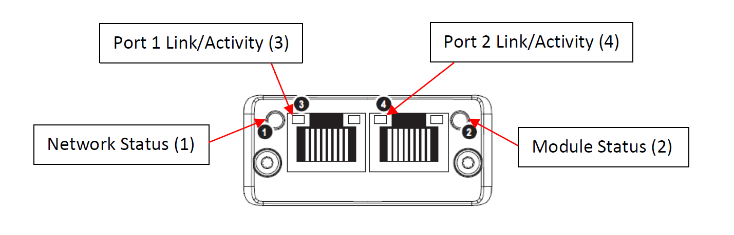
10.3 Network LEDs
There are four network status LEDs on the EthernetIP communications module. They are for the network status, module status, port 1 link/activity, and port 2 link/activity. The LEDs are arranged as shown below.
Network Status LED
| Off | No power or no IP address |
| Green | Online, one or more connections established (CIP Class 1 or 3) |
| Flashing Green | Online, no connections established |
| Red | Duplicate IP address, FATAL error |
| Flashing Red | One or more connections timed out (CIP Class 1 or 3) |
Module Status LED
| Off | No link, no activity |
| Green | Link (100 Mbit/s) established |
| Flickering Green | Activity (100 Mbit/s) |
| Yellow | Link (10 Mbit/s) established |
| Flickering Yellow | Activity (10 Mbit/s) |
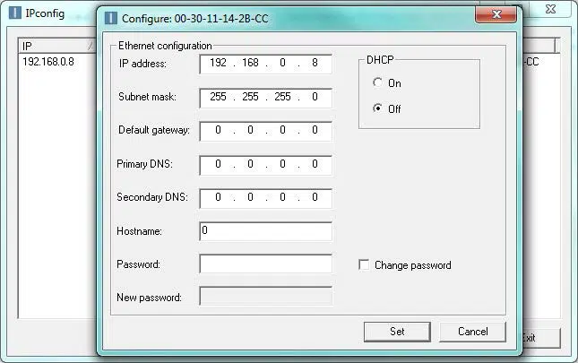
10.4 DHCP and Configuring the IP Address
The user can enable or disable DHCP mode for the EthernetIP communications module. Standard units are shipped with DHCP mode disabled unless explicitly requested otherwise. This simplifies the process for users to assign their own IP addresses, subnet masks, and gateways. Unit IP addresses must be set individually, as multiple default addresses on the same network will cause network conflicts. Default values for the EthernetIP communications module are the following:
| Default IP Address | 192.168.1.8 |
| Default Subnet Mask | 255.255.255.0 |
| Default Gateway | 0.0.0.0 |
To configure the IP address, download the free Ipconfig utility directly from HMS. The Ipconfig utility allows users to change the network settings for the module. Follow the link and see the steps below for downloading and using Ipconfig: https://www.hms-networks.com/support/general-downloads
After an IP address has been set, or if the unit has DHCP mode enabled, settings can be modified through the web server as described in Section 10.5. Refer to Televac® Application Note 3017 for more information on setup and troubleshooting.
- Download the application from HMS.
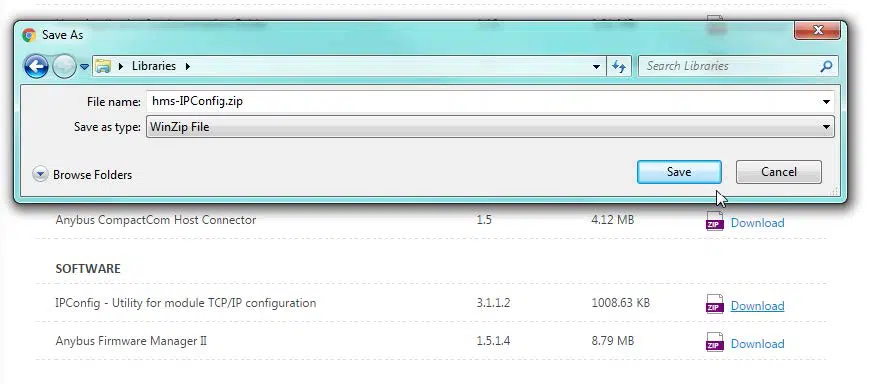
- Launch the application and find the Televac® EthernetIP device.
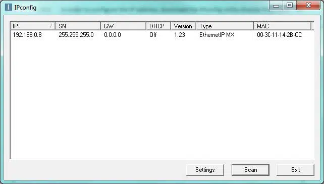
- Modify the settings.
10.5 Web Server
The EthernetIP communications module comes with a built-in web server that can host a password protected web page. With this feature, the user can remotely update all network and module settings, view all MX200 channel data, change any MX200 settings available through the serial port, and view all current EthernetIP networking session statistics. To use the web page, type the IP address into a web browser and enter the username and password. This feature can be disabled during factory programming upon request.
Passwords for the web server can be set either by the factory or by the user. All passwords are saved in a file called web_accs.cfg loaded into the firmware of the module. Passwords can be modified, created, or deleted by using a File Transfer Protocol to modify the configuration file. The default username and password are factory set to ‘Admin’ and ‘admin’, unless otherwise requested.
10.6 EDS Information
For ease of integration and use with a PLC, an Electronic Data Sheet (EDS) file is provided by The Fredericks Company for use with the EthernetIP communications module. An EDS file contains information about the EthernetIP device on the network so that it may be easily identified and connected to from the PLC. By downloading the file to the PLC, the controller will have all important identification and connection information about the MX EthernetIP module.
The EDS file contains all of the MX EthernetIP device identification information, as well as all parameter data information and link paths. The Assembly section of the EDS file contains information on available Class 1 cyclic connections, and the Params section contains information on all available Class 3 acyclic connections, including description, value, read/write information, and a link path. Please refer to Televac® Application Note 3016 for information on how to download an EDS to a Rockwell Automation Allen-Bradley CompactLogix PLC.
10.7 ADI Table
The MX200 EthernetIP module utilizes Application Data Instances within the Application Data Object to transfer information to and from the unit. Every parameter in the unit is represented by a data instance within the data object and has nine attributes that hold information about the parameter. The nine attributes are described in the table below:
| Attribute # | Name | Access | Type | Value/Description |
| 1 | Name | Get | SHORT_STRING | Parameter name (including length) |
| 2 | Data Type | Get | USINT | Data type of instance value |
| 3 | Number of Elements | Get | USINT | Number of elements in the data type |
| 4 | Descriptor | Get | USINT | Bit field describing the access rights for this instance; 0 (Get) = Get Access, 1 (Set) = Set Access |
| 5 | Value | Get/Set | See Attr. #2 | Instance value |
| 6 | Max Value | Get | See Attr. #2 | Maximum parameter value |
| 7 | Min Value | Get | See Attr. #2 | Minimum parameter value |
| 8 | Default Value | Get | See Attr. #2 | The default parameter value |
| 9 | Number of Sub Elements | Get | USINT | Number of sub elements in the ADI, default value is 1 |
To access information about a parameter, a specific attribute of a specific data instance will need to be requested with a Class 3 connection request. The table in Section 1 describes the available data instances and provides some important attribute values for convenience. As an example, to request the value of the Logic Firmware, the PLC programmer would set up a Class 3 request to attribute five (the value attribute) of instance two (the Logic Firmware parameter) in the class A2 object (the Application Data Instance Object). The EthernetIP module will return the firmware value to the programmer in the form of six UINT8 characters.
| Instance | Name | Data Type | Array Length | Access | Data Format | Data Description |
| 2 | Logic Firmware | SHORT_STRING | 6 | Get | XXXXXX | Logic firmware version |
| 3 | Display Firmware | SHORT_STRING | 6 | Get | XXXXXX | Display firmware version |
| 4 | Pressure Units | SHORT_STRING | 2 | Get/Set | XX | Measurement units: PA = Pascal, TR = Torr, MB = mbar, TD = Torr decimal, MT = mTorr |
| 6 | Cold Cathode Mode | SHORT_STRING | 1 | Get/Set | A | Cold cathode mode: 1 = auto, 2 = self |
| 8 | Cold Cathode On Value | SHORT_STRING | 2 | Get/Set | BB | Cold cathode switch point value: BB = 01 to 50 |
| 10 | Cold Cathode Odd Even Value | SHORT_STRING | 2 | Get/Set | CD | Cold cathode status odd and even (on/off). C = odd, D = even, 0 = off, 1 = on |
| 12 | Channel Types | SHORT_STRING | 60 | Get | XX=YY … XX=YY | XX = channel number, YY = sensor type |
| 14 | Set Point Status | SHORT_STRING | 48 | Get | XX=YY … XX=YY | Set point XX status YY: ON = on, OF = off, 00 = no set point connected |
| 15 | Connected Channels | SHORT_STRING | 30 | Get | 01 02 03 … | Channel numbers connected to the unit (unconnected channels read “00”) |
| 16 | Return to Measurement Screen | SHORT_STRING | 1 | Set | M | Go to measurement screen: M = 0 |
| 17 | Restore Global Defaults | SHORT_STRING | 1 | Set | D | Restore Global Setup defaults: D = 0 |
| 18 | Serial Number | SHORT_STRING | 6 | Get | NNNNNN | Six-digit serial number of the unit: 000000 to 999999 |
| 20 | Restore Setup Ch1 Defaults | SHORT_STRING | 2 | Set | XX | Restore Ch1 setup defaults: XX = 00 |
| 21 | Restore Setup Ch2 Defaults | SHORT_STRING | 2 | Set | XX | Restore Ch2 setup defaults: XX = 00 |
| 22 | Restore Setup Ch3 Defaults | SHORT_STRING | 2 | Set | XX | Restore Ch3 setup defaults: XX = 00 |
| 23 | Restore Setup Ch4 Defaults | SHORT_STRING | 2 | Set | XX | Restore Ch4 setup defaults: XX = 00 |
| 24 | Restore Setup Ch5 Defaults | SHORT_STRING | 2 | Set | XX | Restore Ch5 setup defaults: XX = 00 |
| 25 | Restore Setup Ch6 Defaults | SHORT_STRING | 2 | Set | XX | Restore Ch6 setup defaults: XX = 00 |
| 26 | Restore Setup Ch7 Defaults | SHORT_STRING | 2 | Set | XX | Restore Ch7 setup defaults: XX = 00 |
| 27 | Restore Setup Ch8 Defaults | SHORT_STRING | 2 | Set | XX | Restore Ch8 setup defaults: XX = 00 |
| 28 | Restore Setup Ch9 Defaults | SHORT_STRING | 2 | Set | XX | Restore Ch9 setup defaults: XX = 00 |
| 29 | Restore Setup Ch10 Defaults | SHORT_STRING | 2 | Set | XX | Restore Ch10 setup defaults: XX = 00 |
| 30 | Restore Set Point 1 Defaults | SHORT_STRING | 1 | Set | X | Restore SP1 defaults: X = 0 |
| 31 | Restore Set Point 2 Defaults | SHORT_STRING | 1 | Set | X | Restore SP2 defaults: X = 0 |
| 32 | Restore Set Point 3 Defaults | SHORT_STRING | 1 | Set | X | Restore SP3 defaults: X = 0 |
| 33 | Restore Set Point 4 Defaults | SHORT_STRING | 1 | Set | X | Restore SP4 defaults: X = 0 |
| 34 | Restore Set Point 5 Defaults | SHORT_STRING | 1 | Set | X | Restore SP5 defaults: X = 0 |
| 35 | Restore Set Point 6 Defaults | SHORT_STRING | 1 | Set | X | Restore SP6 defaults: X = 0 |
| 36 | Restore Set Point 7 Defaults | SHORT_STRING | 1 | Set | X | Restore SP7 defaults: X = 0 |
| 37 | Restore Set Point 8 Defaults | SHORT_STRING | 1 | Set | X | Restore SP8 defaults: X = 0 |
| 40 | Restore Calibration Ch1 Defaults | SHORT_STRING | 2 | Set | XX | Restore Ch1 calibration defaults: XX = 00 |
| 41 | Restore Calibration Ch2 Defaults | SHORT_STRING | 2 | Set | XX | Restore Ch2 calibration defaults: XX = 00 |
| 42 | Restore Calibration Ch3 Defaults | SHORT_STRING | 2 | Set | XX | Restore Ch3 calibration defaults: XX = 00 |
| 43 | Restore Calibration Ch4 Defaults | SHORT_STRING | 2 | Set | XX | Restore Ch4 calibration defaults: XX = 00 |
| 44 | Restore Calibration Ch5 Defaults | SHORT_STRING | 2 | Set | XX | Restore Ch5 calibration defaults: XX = 00 |
| 45 | Restore Calibration Ch6 Defaults | SHORT_STRING | 2 | Set | XX | Restore Ch6 calibration defaults: XX = 00 |
| 46 | Restore Calibration Ch7 Defaults | SHORT_STRING | 2 | Set | XX | Restore Ch7 calibration defaults: XX = 00 |
| 47 | Restore Calibration Ch8 Defaults | SHORT_STRING | 2 | Set | XX | Restore Ch8 calibration defaults: XX = 00 |
| 48 | Restore Calibration Ch9 Defaults | SHORT_STRING | 2 | Set | XX | Restore Ch9 calibration defaults: XX = 00 |
| 49 | Restore Calibration Ch10 Defaults | SHORT_STRING | 2 | Set | XX | Restore Ch10 calibration defaults: XX = 00 |
| 50 | Baud Rate | SHORT_STRING | 4 | Get/Set | XXXX | Baud rate: 0096 = 9600, 0192 = 19200, 0384 = 38400, 0576 = 57600, 1152 = 115200 |
| 51 | RS485 Address | SHORT_STRING | 2 | Get/Set | XX | RS-485 address: XX = 00 to 99 |
| 52 | Communication Type | SHORT_STRING | 1 | Get/Set | N | Communication type N: 1 = RS-232, 2 = RS-485, 3 = USB, 4 = EIP/PROFINET |
| 99 | Error Checking | SHORT_STRING | 8 | Get | NNNNNNNN | Displays error received, or “OK” for no error |
| 101 | Pressure Ch1 | REAL | 1 | Get/PD_READ | BBBB | Ch1 pressure output, REAL as 4 hex bytes |
| 201 | Pressure Ch2 | REAL | 1 | Get/PD_READ | BBBB | Ch2 pressure output, REAL as 4 hex bytes |
| 301 | Pressure Ch3 | REAL | 1 | Get/PD_READ | BBBB | Ch3 pressure output, REAL as 4 hex bytes |
| 401 | Pressure Ch4 | REAL | 1 | Get/PD_READ | BBBB | Ch4 pressure output, REAL as 4 hex bytes |
| 501 | Pressure Ch5 | REAL | 1 | Get/PD_READ | BBBB | Ch5 pressure output, REAL as 4 hex bytes |
| 601 | Pressure Ch6 | REAL | 1 | Get/PD_READ | BBBB | Ch6 pressure output, REAL as 4 hex bytes |
| 701 | Pressure Ch7 | REAL | 1 | Get/PD_READ | BBBB | Ch7 pressure output, REAL as 4 hex bytes |
| 801 | Pressure Ch8 | REAL | 1 | Get/PD_READ | BBBB | Ch8 pressure output, REAL as 4 hex bytes |
| 901 | Pressure Ch9 | REAL | 1 | Get/PD_READ | BBBB | Ch9 pressure output, REAL as 4 hex bytes |
| 1001 | Pressure Ch10 | REAL | 1 | Get/PD_READ | BBBB | Ch10 pressure output, REAL as 4 hex bytes |
| 11 | Output Real | REAL | 4 | PD_WRITE | BBBB | Send 4 arbitrary hex bytes to begin Class 1 connection |
| 102 | Calibration 1 Ch1 | SHORT_STRING | 3 | Get/Set | Baa | Calibration point 1 for Ch1: B = 0 or 1 (negative/positive), aa = 00 to 99 |
| 202 | Calibration 1 Ch2 | SHORT_STRING | 3 | Get/Set | Baa | Calibration point 1 for Ch2: B = 0 or 1 (negative/positive), aa = 00 to 99 |
| 302 | Calibration 1 Ch3 | SHORT_STRING | 3 | Get/Set | Baa | Calibration point 1 for Ch3: B = 0 or 1 (negative/positive), aa = 00 to 99 |
| 402 | Calibration 1 Ch4 | SHORT_STRING | 3 | Get/Set | Baa | Calibration point 1 for Ch4: B = 0 or 1 (negative/positive), aa = 00 to 99 |
| 502 | Calibration 1 Ch5 | SHORT_STRING | 3 | Get/Set | Baa | Calibration point 1 for Ch5: B = 0 or 1 (negative/positive), aa = 00 to 99 |
| 602 | Calibration 1 Ch6 | SHORT_STRING | 3 | Get/Set | Baa | Calibration point 1 for Ch6: B = 0 or 1 (negative/positive), aa = 00 to 99 |
| 702 | Calibration 1 Ch7 | SHORT_STRING | 3 | Get/Set | Baa | Calibration point 1 for Ch7: B = 0 or 1 (negative/positive), aa = 00 to 99 |
| 802 | Calibration 1 Ch8 | SHORT_STRING | 3 | Get/Set | Baa | Calibration point 1 for Ch8: B = 0 or 1 (negative/positive), aa = 00 to 99 |
| 902 | Calibration 1 Ch9 | SHORT_STRING | 3 | Get/Set | Baa | Calibration point 1 for Ch9: B = 0 or 1 (negative/positive), aa = 00 to 99 |
| 1002 | Calibration 1 Ch10 | SHORT_STRING | 3 | Get/Set | Baa | Calibration point 1 for Ch10: B = 0 or 1 (negative/positive), aa = 00 to 99 |
| 104 | Calibration 2 Ch1 | SHORT_STRING | 3 | Get/Set | Baa | Calibration point 2 for Ch1: B = 0 or 1 (negative/positive), aa = 00 to 99 |
| 204 | Calibration 2 Ch2 | SHORT_STRING | 3 | Get/Set | Baa | Calibration point 2 for Ch2: B = 0 or 1 (negative/positive), aa = 00 to 99 |
| 304 | Calibration 2 Ch3 | SHORT_STRING | 3 | Get/Set | Baa | Calibration point 2 for Ch3: B = 0 or 1 (negative/positive), aa = 00 to 99 |
| 404 | Calibration 2 Ch4 | SHORT_STRING | 3 | Get/Set | Baa | Calibration point 2 for Ch4: B = 0 or 1 (negative/positive), aa = 00 to 99 |
| 504 | Calibration 2 Ch5 | SHORT_STRING | 3 | Get/Set | Baa | Calibration point 2 for Ch5: B = 0 or 1 (negative/positive), aa = 00 to 99 |
| 604 | Calibration 2 Ch6 | SHORT_STRING | 3 | Get/Set | Baa | Calibration point 2 for Ch6: B = 0 or 1 (negative/positive), aa = 00 to 99 |
| 704 | Calibration 2 Ch7 | SHORT_STRING | 3 | Get/Set | Baa | Calibration point 2 for Ch7: B = 0 or 1 (negative/positive), aa = 00 to 99 |
| 804 | Calibration 2 Ch8 | SHORT_STRING | 3 | Get/Set | Baa | Calibration point 2 for Ch8: B = 0 or 1 (negative/positive), aa = 00 to 99 |
| 904 | Calibration 2 Ch9 | SHORT_STRING | 3 | Get/Set | Baa | Calibration point 2 for Ch9: B = 0 or 1 (negative/positive), aa = 00 to 99 |
| 1004 | Calibration 2 Ch10 | SHORT_STRING | 3 | Get/Set | Baa | Calibration point 2 for Ch10: B = 0 or 1 (negative/positive), aa = 00 to 99 |
| 106 | Calibration 3 Ch1 | SHORT_STRING | 3 | Get/Set | Baa | Calibration point 3 for Ch1: B = 0 or 1 (negative/positive), aa = 00 to 99 |
| 206 | Calibration 3 Ch2 | SHORT_STRING | 3 | Get/Set | Baa | Calibration point 3 for Ch2: B = 0 or 1 (negative/positive), aa = 00 to 99 |
| 306 | Calibration 3 Ch3 | SHORT_STRING | 3 | Get/Set | Baa | Calibration point 3 for Ch3: B = 0 or 1 (negative/positive), aa = 00 to 99 |
| 406 | Calibration 3 Ch4 | SHORT_STRING | 3 | Get/Set | Baa | Calibration point 3 for Ch4: B = 0 or 1 (negative/positive), aa = 00 to 99 |
| 506 | Calibration 3 Ch5 | SHORT_STRING | 3 | Get/Set | Baa | Calibration point 3 for Ch5: B = 0 or 1 (negative/positive), aa = 00 to 99 |
| 606 | Calibration 3 Ch6 | SHORT_STRING | 3 | Get/Set | Baa | Calibration point 3 for Ch6: B = 0 or 1 (negative/positive), aa = 00 to 99 |
| 706 | Calibration 3 Ch7 | SHORT_STRING | 3 | Get/Set | Baa | Calibration point 3 for Ch7: B = 0 or 1 (negative/positive), aa = 00 to 99 |
| 806 | Calibration 3 Ch8 | SHORT_STRING | 3 | Get/Set | Baa | Calibration point 3 for Ch8: B = 0 or 1 (negative/positive), aa = 00 to 99 |
| 906 | Calibration 3 Ch9 | SHORT_STRING | 3 | Get/Set | Baa | Calibration point 3 for Ch9: B = 0 or 1 (negative/positive), aa = 00 to 99 |
| 1006 | Calibration 3 Ch10 | SHORT_STRING | 3 | Get/Set | Baa | Calibration point 3 for Ch10: B = 0 or 1 (negative/positive), aa = 00 to 99 |
| 108 | Calibration 4 Ch1 | SHORT_STRING | 3 | Get/Set | Baa | Calibration point 4 for Ch1: B = 0 or 1 (negative/positive), aa = 00 to 99 |
| 208 | Calibration 4 Ch2 | SHORT_STRING | 3 | Get/Set | Baa | Calibration point 4 for Ch2: B = 0 or 1 (negative/positive), aa = 00 to 99 |
| 308 | Calibration 4 Ch3 | SHORT_STRING | 3 | Get/Set | Baa | Calibration point 4 for Ch3: B = 0 or 1 (negative/positive), aa = 00 to 99 |
| 408 | Calibration 4 Ch4 | SHORT_STRING | 3 | Get/Set | Baa | Calibration point 4 for Ch4: B = 0 or 1 (negative/positive), aa = 00 to 99 |
| 508 | Calibration 4 Ch5 | SHORT_STRING | 3 | Get/Set | Baa | Calibration point 4 for Ch5: B = 0 or 1 (negative/positive), aa = 00 to 99 |
| 608 | Calibration 4 Ch6 | SHORT_STRING | 3 | Get/Set | Baa | Calibration point 4 for Ch6: B = 0 or 1 (negative/positive), aa = 00 to 99 |
| 708 | Calibration 4 Ch7 | SHORT_STRING | 3 | Get/Set | Baa | Calibration point 4 for Ch7: B = 0 or 1 (negative/positive), aa = 00 to 99 |
| 808 | Calibration 4 Ch8 | SHORT_STRING | 3 | Get/Set | Baa | Calibration point 4 for Ch8: B = 0 or 1 (negative/positive), aa = 00 to 99 |
| 908 | Calibration 4 Ch9 | SHORT_STRING | 3 | Get/Set | Baa | Calibration point 4 for Ch9: B = 0 or 1 (negative/positive), aa = 00 to 99 |
| 1008 | Calibration 4 Ch10 | SHORT_STRING | 3 | Get/Set | Baa | Calibration point 4 for Ch10: B = 0 or 1 (negative/positive), aa = 00 to 99 |
| 110 | Calibration 5 Ch1 | SHORT_STRING | 3 | Get/Set | Baa | Calibration point 5 for Ch1: B = 0 or 1 (negative/positive), aa = 00 to 99 |
| 210 | Calibration 5 Ch2 | SHORT_STRING | 3 | Get/Set | Baa | Calibration point 5 for Ch2: B = 0 or 1 (negative/positive), aa = 00 to 99 |
| 310 | Calibration 5 Ch3 | SHORT_STRING | 3 | Get/Set | Baa | Calibration point 5 for Ch3: B = 0 or 1 (negative/positive), aa = 00 to 99 |
| 410 | Calibration 5 Ch4 | SHORT_STRING | 3 | Get/Set | Baa | Calibration point 5 for Ch4: B = 0 or 1 (negative/positive), aa = 00 to 99 |
| 510 | Calibration 5 Ch5 | SHORT_STRING | 3 | Get/Set | Baa | Calibration point 5 for Ch5: B = 0 or 1 (negative/positive), aa = 00 to 99 |
| 610 | Calibration 5 Ch6 | SHORT_STRING | 3 | Get/Set | Baa | Calibration point 5 for Ch6: B = 0 or 1 (negative/positive), aa = 00 to 99 |
| 710 | Calibration 5 Ch7 | SHORT_STRING | 3 | Get/Set | Baa | Calibration point 5 for Ch7: B = 0 or 1 (negative/positive), aa = 00 to 99 |
| 810 | Calibration 5 Ch8 | SHORT_STRING | 3 | Get/Set | Baa | Calibration point 5 for Ch8: B = 0 or 1 (negative/positive), aa = 00 to 99 |
| 910 | Calibration 5 Ch9 | SHORT_STRING | 3 | Get/Set | Baa | Calibration point 5 for Ch9: B = 0 or 1 (negative/positive), aa = 00 to 99 |
| 1010 | Calibration 5 Ch10 | SHORT_STRING | 3 | Get/Set | Baa | Calibration point 5 for Ch10: B = 0 or 1 (negative/positive), aa = 00 to 99 |
| 114 | Channel Display Ch1 | SHORT_STRING | 2 | Get/Set | XX | Toggle Ch1 on the measurement screen: XX=00 (Set), XX=ON or OF (Get) |
| 214 | Channel Display Ch2 | SHORT_STRING | 2 | Get/Set | XX | Toggle Ch1 on the measurement screen: XX=00 (Set), XX=ON or OF (Get) |
| 314 | Channel Display Ch3 | SHORT_STRING | 2 | Get/Set | XX | Toggle Ch1 on the measurement screen: XX=00 (Set), XX=ON or OF (Get) |
| 414 | Channel Display Ch4 | SHORT_STRING | 2 | Get/Set | XX | Toggle Ch1 on the measurement screen: XX=00 (Set), XX=ON or OF (Get) |
| 514 | Channel Display Ch5 | SHORT_STRING | 2 | Get/Set | XX | Toggle Ch1 on the measurement screen: XX=00 (Set), XX=ON or OF (Get) |
| 614 | Channel Display Ch6 | SHORT_STRING | 2 | Get/Set | XX | Toggle Ch1 on the measurement screen: XX=00 (Set), XX=ON or OF (Get) |
| 714 | Channel Display Ch7 | SHORT_STRING | 2 | Get/Set | XX | Toggle Ch1 on the measurement screen: XX=00 (Set), XX=ON or OF (Get) |
| 814 | Channel Display Ch8 | SHORT_STRING | 2 | Get/Set | XX | Toggle Ch1 on the measurement screen: XX=00 (Set), XX=ON or OF (Get) |
| 914 | Channel Display Ch9 | SHORT_STRING | 2 | Get/Set | XX | Toggle Ch1 on the measurement screen: XX=00 (Set), XX=ON or OF (Get) |
| 1014 | Channel Display Ch10 | SHORT_STRING | 2 | Get/Set | XX | Toggle Ch1 on the measurement screen: XX=00 (Set), XX=ON or OF (Get) |
| 116 | Analog Output Ch1 | SHORT_STRING | 7 | Get/Set | FbaaBAA | Ch1 analog output format: F = 1 or 2 (lin/log), baa = high value, BAA = low value |
| 216 | Analog Output Ch2 | SHORT_STRING | 7 | Get/Set | FbaaBAA | Ch2 analog output format: F = 1 or 2 (lin/log), baa = high value, BAA = low value |
| 316 | Analog Output Ch3 | SHORT_STRING | 7 | Get/Set | FbaaBAA | Ch3 analog output format: F = 1 or 2 (lin/log), baa = high value, BAA = low value |
| 416 | Analog Output Ch4 | SHORT_STRING | 7 | Get/Set | FbaaBAA | Ch4 analog output format: F = 1 or 2 (lin/log), baa = high value, BAA = low value |
| 516 | Analog Output Ch5 | SHORT_STRING | 7 | Get/Set | FbaaBAA | Ch5 analog output format: F = 1 or 2 (lin/log), baa = high value, BAA = low value |
| 616 | Analog Output Ch6 | SHORT_STRING | 7 | Get/Set | FbaaBAA | Ch6 analog output format: F = 1 or 2 (lin/log), baa = high value, BAA = low value |
| 716 | Analog Output Ch7 | SHORT_STRING | 7 | Get/Set | FbaaBAA | Ch7 analog output format: F = 1 or 2 (lin/log), baa = high value, BAA = low value |
| 816 | Analog Output Ch8 | SHORT_STRING | 7 | Get/Set | FbaaBAA | Ch8 analog output format: F = 1 or 2 (lin/log), baa = high value, BAA = low value |
| 916 | Analog Output Ch9 | SHORT_STRING | 7 | Get/Set | FbaaBAA | Ch9 analog output format: F = 1 or 2 (lin/log), baa = high value, BAA = low value |
| 1016 | Analog Output Ch10 | SHORT_STRING | 7 | Get/Set | FbaaBAA | Ch10 analog output format: F = 1 or 2 (lin/log), baa = high value, BAA = low value |
| 118 | Gas Type Ch1 | SHORT_STRING | 2 | Get/Set | GG | Gas type setting for channel 1 |
| 218 | Gas Type Ch2 | SHORT_STRING | 2 | Get/Set | GG | Gas type setting for channel 2 |
| 318 | Gas Type Ch3 | SHORT_STRING | 2 | Get/Set | GG | Gas type setting for channel 3 |
| 418 | Gas Type Ch4 | SHORT_STRING | 2 | Get/Set | GG | Gas type setting for channel 4 |
| 518 | Gas Type Ch5 | SHORT_STRING | 2 | Get/Set | GG | Gas type setting for channel 5 |
| 618 | Gas Type Ch6 | SHORT_STRING | 2 | Get/Set | GG | Gas type setting for channel 6 |
| 718 | Gas Type Ch7 | SHORT_STRING | 2 | Get/Set | GG | Gas type setting for channel 7 |
| 818 | Gas Type Ch8 | SHORT_STRING | 2 | Get/Set | GG | Gas type setting for channel 8 |
| 918 | Gas Type Ch9 | SHORT_STRING | 2 | Get/Set | GG | Gas type setting for channel 9 |
| 1018 | Gas Type Ch10 | SHORT_STRING | 2 | Get/Set | GG | Gas type setting for channel 10 |
| 120 | Set Point 1 | SHORT_STRING | 12 | Get/Set | ppseePPSEEZZ | Set point 1 settings: on = ppsee, off = PPSEE, channel = ZZ |
| 220 | Set Point 2 | SHORT_STRING | 12 | Get/Set | ppseePPSEEZZ | Set point 1 settings: on = ppsee, off = PPSEE, channel = ZZ |
| 320 | Set Point 3 | SHORT_STRING | 12 | Get/Set | ppseePPSEEZZ | Set point 1 settings: on = ppsee, off = PPSEE, channel = ZZ |
| 420 | Set Point 4 | SHORT_STRING | 12 | Get/Set | ppseePPSEEZZ | Set point 1 settings: on = ppsee, off = PPSEE, channel = ZZ |
| 520 | Set Point 5 | SHORT_STRING | 12 | Get/Set | ppseePPSEEZZ | Set point 1 settings: on = ppsee, off = PPSEE, channel = ZZ |
| 620 | Set Point 6 | SHORT_STRING | 12 | Get/Set | ppseePPSEEZZ | Set point 1 settings: on = ppsee, off = PPSEE, channel = ZZ |
| 720 | Set Point 7 | SHORT_STRING | 12 | Get/Set | ppseePPSEEZZ | Set point 1 settings: on = ppsee, off = PPSEE, channel = ZZ |
| 820 | Set Point 8 | SHORT_STRING | 12 | Get/Set | ppseePPSEEZZ | Set point 1 settings: on = ppsee, off = PPSEE, channel = ZZ |
| 122 | Resolution Ch1 | SHORT_STRING | 2 | Get/Set | XX | Toggle Ch1 resolution: XX = 00 (Set), XX = HI or LO (Get) |
| 222 | Resolution Ch2 | SHORT_STRING | 2 | Get/Set | XX | Toggle Ch1 resolution: XX = 00 (Set), XX = HI or LO (Get) |
| 322 | Resolution Ch3 | SHORT_STRING | 2 | Get/Set | XX | Toggle Ch1 resolution: XX = 00 (Set), XX = HI or LO (Get) |
| 422 | Resolution Ch4 | SHORT_STRING | 2 | Get/Set | XX | Toggle Ch1 resolution: XX = 00 (Set), XX = HI or LO (Get) |
| 522 | Resolution Ch5 | SHORT_STRING | 2 | Get/Set | XX | Toggle Ch1 resolution: XX = 00 (Set), XX = HI or LO (Get) |
| 622 | Resolution Ch6 | SHORT_STRING | 2 | Get/Set | XX | Toggle Ch1 resolution: XX = 00 (Set), XX = HI or LO (Get) |
| 722 | Resolution Ch7 | SHORT_STRING | 2 | Get/Set | XX | Toggle Ch1 resolution: XX = 00 (Set), XX = HI or LO (Get) |
| 822 | Resolution Ch8 | SHORT_STRING | 2 | Get/Set | XX | Toggle Ch1 resolution: XX = 00 (Set), XX = HI or LO (Get) |
| 922 | Resolution Ch9 | SHORT_STRING | 2 | Get/Set | XX | Toggle Ch1 resolution: XX = 00 (Set), XX = HI or LO (Get) |
| 1022 | Resolution Ch10 | SHORT_STRING | 2 | Get/Set | XX | Toggle Ch1 resolution: XX = 00 (Set), XX = HI or LO (Get) |
11. PROFINET
11.1 PROFINET Interface Description
The PROFINET module allows for the transmission of data and the configuration of the MX200 over the standardized PROFINET protocol.
The PROFINET interface provides cyclic access to pressure readings and setpoint values over the PROFINET RT network. Additionally, all other configuration options present in the MX200 are available over acyclic communication.
The MX200’s communication mode must be set to PROFINET to properly communicate with the PROFINET network. Failure to do this will result in invalid readings.
11.2 Network LEDs
There are four network status LEDs on the PROFINET communications module. They are for the network status, module status, port 1 link/activity, and port 2 link/activity. The LEDs are arranged as shown below.
Network Status LED
| Off | No power or no connection with IO Controller |
| Green | Connection with IO Controller, IO Controller in RUN state |
| Green, 1 Flash | Connection with IO Controller, IO Controller in STOP state or bad IO data |
| Flashing Green | Used by engineering tools to identify device on the network |
| Red | Error (usually combined with red module status LED) |
| Red, 1 Flash | Station Name not set |
| Red, 2 Flashes | IP address not set |
| Red, 3 Flashes | Expected Identification differs from Real Identification |
Module Status LED
| Off | No power or initializing |
| Green | Module is running normally |
| Green, 1 Flash | Diagnostic Event |
| Red | EXCEPTION state or major error |
| Alternating Red/Green | Do not power off system. Powering off the system could cause permanent damage |
Link/Activity LED
| Off | No link, no activity |
| Green | Link (100 Mbit/s) established, no communication |
| Flickering Green | Link (100 Mbit/s) established, active communication |
11.3 Cyclic Parameters
General settings
| Name | Data Type | Data Size | Access | Notes |
| Pressure | REAL[10] | 4[40] | Get | Contains array of 10 real values. First value is Channel 1, second is channel 2, etc. |
| Setpoints | BITS[8] | 1 | Get | 8 bits for the 8 setpoint relays. 1=TRIPPED 0=NOT TRIPPED |
11.4 Acyclic Parameters
General settings
| Index | Name | Data Type | Data Size | Access | Notes |
| 0x03 | Logic Firmware Version | UINT32 | 4 | Get | |
| 0x04 | Display Firmware Version | UINT32 | 4 | Get | |
| 0x05 | Serial Number | CHAR[6] | 1[6] | Get | |
| 0x06 | Pressure Units | UINT8 | 1 | Get/Set | 1=TORR, 2=MBAR, 3=PASCAL, 4=TORR DECIMAL, 5=MTORR, 0=ERROR |
| 0x07 | Cold Cathode Mode | UINT8 | 1 | Get/Set | 1=AUTO, 2=SELF, 0=ERROR |
| 0x08 | Cold Cathode Enabled | BITS[2] | 1 | Get/Set | First bit represents even cold cathodes, second represents odd. 1=ON, 0=OFF |
| 0x09 | Cold Cathode Switch Point | UINT8 | 1 | Get/Set | Represents the mTorr value that the cold cathode will turn on at. |
| 0x0a | Set Channel Defaults | BITS[16] | 2 | Set | Set the first bit to 1 to reset ch1, second bit to reset ch2, etc. |
| 0x0b | Set Calibration Defaults | BITS[16] | 2 | Set | Set the first bit to 1 to reset ch1, second bit to reset ch2, etc. |
| 0x0c | Set Setpoint Defaults | BITS[8] | 1 | Set | Set the first bit to 1 to reset sp1, second bit to reset sp2, etc. |
Channel settings
| Index | Name | Data Type | Data Size | Access | Notes |
| 0x10 | Ch 1 Sensor Type | UINT8 | 1 | Get | 1=1E, 2=1F, 3=2A, 4=4A, 5=5A, 6=5B, 7=5C, 8=5D, 9=5E, 10=7B, 11=7EF, 0=ERROR |
| 0x11 | Ch 1 Connected | BOOL | 1 | Get | |
| 0x12 | Ch 1 Resolution | UINT8 | 1 | Get/Set | 1=LOW, 2=HIGH, 0=ERROR |
| 0x13 | Ch 1 Display Enabled | BOOL | 1 | Get/Set | Controls whether the value is shown on the MX200’s display |
| 0x14 | Ch 1 Gas Type | UINT8 | 1 | Get/Set | 1=N2, 2=AR, 3=H2, 4=HE, 5=NE, 6=KR, 7=CO, 0=UNKNOWN |
| 0x15 | Ch 1 Analog | CHAR[7] | 1[7] | Get/Set | See 0 |
| 0x16 | Ch 1 Calibration | UINT8[5] | 1[5] | Get/Set | The integer values of the 5 calibration points for the channel |
| 0x20-0x26 | Ch 2 Settings | See 0x10-0x16 | |||
| 0x30-0x36 | Ch 3 Settings | See 0x10-0x16 | |||
| 0x40-0x46 | Ch 4 Settings | See 0x10-0x16 | |||
| 0x50-0x56 | Ch 5 Settings | See 0x10-0x16 | |||
| 0x60-0x66 | Ch 6 Settings | See 0x10-0x16 | |||
| 0x70-0x76 | Ch 7 Settings | See 0x10-0x16 | |||
| 0x80-0x86 | Ch 8 Settings | See 0x10-0x16 | |||
| 0x90-0x96 | Ch 9 Settings | See 0x10-0x16 | |||
| 0xa0-0xa6 | Ch 10 Settings | See 0x10-0x16 |
| Index | Name | Data Type | Data Size | Access | Notes |
| 0xf0 | Setpoint 1 Settings | CHAR[12] | 1[12] | Get/Set | See Section 9.10 |
| 0xf1 | Setpoint 2 Settings | CHAR[12] | 1[12] | Get/Set | See Section 9.10 |
| 0xf2 | Setpoint 3 Settings | CHAR[12] | 1[12] | Get/Set | See Section 9.10 |
| 0xf3 | Setpoint 4 Settings | CHAR[12] | 1[12] | Get/Set | See Section 9.10 |
| 0xf4 | Setpoint 5 Settings | CHAR[12] | 1[12] | Get/Set | See Section 9.10 |
| 0xf5 | Setpoint 6 Settings | CHAR[12] | 1[12] | Get/Set | See Section 9.10 |
| 0xf6 | Setpoint 7 Settings | CHAR[12] | 1[12] | Get/Set | See Section 9.10 |
| 0xf7 | Setpoint 8 Settings | CHAR[12] | 1[12] | Get/Set | See Section 9.10 |
12. Analog Outputs
12.1 Description
Each sensor has its own 0 V DC to 10 V DC analog output. Analog outputs are configurable through the front panel or through digital communications and are unique to each sensor. Analog outputs are accessed through a 3 position screw terminal on the sensor module. They are generated by a 16-bit digital to analog converter.
12.2 Changing the Analog Output Function
Changing the Mode (Linear, Logarithmic, and Linear-by-Decade)
To change the analog output mode, press the home button then navigate through the following menus:
Channel Setup > Channel X > Analog Out > Mode
The options are linear, logarithmic, and linear-by-decade (sensor dependent) and the current setting is displayed at the top of the screen. Use the up and down buttons to scroll to the desired mode and press the ENT button to save it. You will see the current setting at the top of the screen change. A more detailed description of these options for each sensor can be found in Section 12.7.
Changing the High and Low Values
To change the high and low values for the analog output, press the home button then navigate through the following menus:
Channel Setup > Channel X > Analog Out > High/Low Value
The high or low value will then be displayed. Use the up and down arrows to adjust the exponent to the desired value and press the ENT button to save it. To exit without saving, press the left or home button without pressing the ENT button.
12.3 Notes on Logarithmic Analog Output Mode
When the analog output is set to logarithmic, both the high and low values can be modified, but there must be at least 3 decades between the high and low values. The software will automatically prevent the user from selecting a high and low value with a range less than 3 decades. Note that for sensors with only 3 decades of range, neither value can be modified.
12.4 Notes on Linear Analog Output Mode
The linear analog output mode is designed so that only the high value is editable. Once a high value is entered, 3 decades below that will be automatically saved as the low value. As an example, if 1.0E-4 is selected as the high value, the low value will be set to 1.0E-7. This is to maintain sufficient output resolution over the range of the 0 to 10 V DC output. Note that when a sensor has only 3 decades of range, the high value cannot be modified. Also note that the user is prevented from picking a high value that is less than 3 decades above the specified lower vacuum measurement range of the sensor.
12.5 Notes on Linear-by-Decade Analog Output Mode
The linear-by-decade analog output mode is designed so that neither the high or low value are editable.
12.6 Refresh Rate
The readings for all vacuum sensors connected to an MX200 are updated at a minimum rate of 100 Hz. The analog outputs for all vacuum sensors connected to an MX200 are updated at a minimum rate of 10 Hz.
12.7 Analog Output Functions
1E Piezo Diaphragm
Linear Conversion
The 1E does not have settable values for the linear analog output. Therefore, the linear conversion from voltage output to pressure will always be the same:
Voltage Output * 102 = Pressure
Example where the voltage output is 0.500 V DC:
0.5*102 = 5.0*101 = 50 Torr
1F Piezo Diaphragm
Linear Conversion
The 1F does not have settable values for the linear analog output. Therefore, the linear conversion from voltage output to pressure will always be the same:
Voltage Output * 103 = Pressure
Example where the voltage output is 0.500 V DC:
0.5*103 = 5.0*102 = 500 Torr
2A Thermocouple
Linear Conversion
The 2A only provides output from 1*10-3 Torr to 1 Torr, so it does not have settable values for the linear analog output. Therefore, the linear conversion from voltage output to pressure will always be the same:
Voltage Output * 10-1 = Pressure
Example where the voltage output is 0.100 V DC:
0.100 * 10-1 = 0.100 / 10 = 0.010 Torr = 1.0*10-2 Torr
Logarithmic Conversion
The 2A only provides output from 1*10-3 Torr to 1 Torr, so it does not have settable values for the logarithmic analog output. Therefore, the logarithmic conversion from voltage output to pressure will always be the same:
1.0*100.3*(Voltage Output – 10) = Pressure
Example where the voltage output is 3.333 V DC:
1.0*100.3*(3.333 – 10) = 1.0*100.3*(-6.667) = 1.0*10-2 Torr = 0.010 Torr
4A Convection Enhanced Thermocouple
Linear Conversion
For the 4A linear analog output, use the high value (1.0*10H) exponent H in the following equation to convert the voltage output to pressure:
Voltage Output * 10(H-1) = Pressure
Example linear output where the voltage output is 0.010 V DC and the high value is 1.0*100. Take the high value exponent 0 for H and use it in the equation above:
0.010 * 10(0-1) = 0.010 * 10-1 = 0.010 / 10 = 0.001 Torr = 1*10-3 Torr
Logarithmic Conversion
The 4A logarithmic analog output has settable high and low values, so they must be taken into consideration when converting the voltage output to pressure:
High Value = 1.0*10H
Low Value = 1.0*10L
C1 = (1/(L-H)) * (-10)
C2 = (1/(L-H)) * 10 * L
1.0*10(1/C1)*(Voltage Output – C2) = Pressure
Example logarithmic output where the voltage output is 1.666 V DC, the high value is 1.0*103, and the low value is 1.0*10-3:
High Value = 1.0*103
Low Value = 1.0*10-3
C1 = (1/(-3-3)) * (-10) = 1.667
C2 = (1/(-3-3)) * 10 * (-3) = 5
1.0*10(1/1.667)*(1.666-5) = 1.0*100.6*(-3.333) = 1.0*10-2 Torr = 0.010 Torr
Linear-by-Decade (L-D) Conversion
The 4A linear-by-decade output has a range of 1*10-3 Torr to 1000 Torr. Neither the high or low values are settable for this analog output, so the linear-by-decade conversion from voltage output to pressure will always be the same:
Voltage Output in V DC = A.BCD
Pressure in Torr = 0.BCD * 10(A-6)
Example linear-by-decade voltage output to pressure conversions:
Voltage Output in V DC = 5.900 V DC
Pressure in Torr = 0.900 * 10(5-6) = 0.900 * 10-1 = 0.090 Torr = 9.0*10-2 Torr
Voltage Output in V DC = 9.300 V DC
Pressure in Torr = 0.300 * 10(9-6) = 0.300 * 103 = 3.0 * 102 Torr
7B Penning Cold Cathode
Linear Conversion
For the 7B linear analog output, use the high value (1.0*10H) exponent H in the following equation to convert the voltage output to pressure:
Voltage Output * 10(H-1) = Pressure
Example linear output where the voltage output is 0.500 V DC and the high value is 1.0*10-4. Take the high value exponent 0 for H and use it in the equation above:
0.500*10(-4-1) = 0.5*10-5 = 5.0*10-6 Torr
Logarithmic Conversion
The 7B logarithmic output has settable high and low values, so they must be taken into consideration when converting the voltage output to pressure:
High Value = 1.0*10H
Low Value = 1.0*10L
C1(1/(L-H)) * (-10)
C2(1/(L-H)) * 10 * L
1.0*10(1/C1)*(Voltage Output – C2) = Pressure
Example logarithmic output where the voltage output is 7.500 V DC, the high value is 1.0*10-3, and the low value is 1.0*10-7:
High Value = 1.0*10-3
Low Value = 1.0*10-7
C1(1/(-7-(-3))) * (-10) = 2.5
C2(1/(-7-(-3))) * 10 * (-7) = 17.5
1.0*10(1/2.5)*(7.500-17.5) = 1.0*100.4*(-10) = 1.0*10-4 Torr
Linear-by-Decade (L-D) Conversion
The 7B linear-by-decade output has a range of 1*10-7 Torr to 1*10-3 Torr. Neither the high or low values are settable for this analog output, so the linear-by-decade conversion from voltage output to pressure will always be the same:
Voltage Output in V DC = A.BCD
A.BCD/2 = E.FGH
Pressure in Torr = 0.FGH * 10(E-7)
Example linear-by-decade voltage output to pressure conversions:
Voltage Output in V DC = 5.800 V DC
5.800/2 = 2.900
Pressure in Torr = 0.900 * 10(2-7) = 0.900 * 10-5 = 9.0 * 10-6 Torr
Voltage Output in V DC = 9.200 V DC
9.200/2 = 4.600
Pressure in Torr = 0.600 * 10(4-7) = 0.600 * 10-3 = 6.0 * 10-4 Torr
7E, 7F, 7FC, 7FCS Double Inverted Magnetron Cold Cathodes
Linear Conversion
For the 7E, 7F, 7FC, and 7FCS linear analog outputs, use the high value (1.0*10H) exponent H in the following equation to convert the voltage output to pressure:
Voltage Output * 10(H-1) = Pressure
Example linear output where the voltage output is 0.500 V DC and the high value is 1.0*10-4. Take the high value exponent 0 for H and use it in the equation above:
0.500*10(-4-1) = 0.5*10-5 = 5.0*10-6 Torr
Logarithmic Conversion
The 7E, 7F, 7FC, and 7FCS logarithmic outputs have settable high and low values, so they must be taken into consideration when converting the voltage output to pressure:
High Value = 1.0*10H
Low Value = 1.0*10L
C1 = (1/(L-H)) * (-10)
C2 = (1/(L-H)) * 10 * L
1.0*10(1/C1)*(Voltage Output – C2) = Pressure
Example logarithmic output where the voltage output is 3.333 V DC, the high value is 1.0*10-11, and the low value is 1.0*10-2:
High Value = 1.0*10-2
Low Value = 1.0*10-11
C1 = (1/(-11-(-2))) * (-10) = 1.111
C2 = (1/(-11-(-2))) * 10 * (-11) = 12.222
1.0*10(1/1.111)*(3.333-12.222) = 1.0*100.9*(-8.888) = 1.0*10-8 Torr
Linear-by-Decade (L-D) Conversion for the 7F, 7FC, and 7FCS
The linear-by-decade output for the 7F, 7FC, and 7FCS has a range of 1*10-11 Torr to 1*10-2 Torr. Neither the high or low values are settable for this analog output, so the linear-by-decade conversion from voltage output to pressure will always be the same:
Voltage Output in V DC = A.BCD
Pressure in Torr = 0.BCD * 10(A-10)
Example linear-by-decade voltage output to pressure conversions:
Voltage Output in V DC = 5.900 V DC
Pressure in Torr = 0.900 * 10(5-10) = 0.900 * 10-5 = 9.0 * 10-6 Torr
Voltage Output in V DC = 1.300 V DC
Pressure in Torr = 0.300 * 10(1-10) = 0.300 * 10-9 = 3.0 * 10-10 Torr
Linear-by-Decade (L-D) Conversion for the 7E
The linear-by-decade output for the 7F, 7FC, and 7FCS has a range of 1*10-8 Torr to 1*10-2 Torr. Neither the high or low values are settable for this analog output, so the linear-by-decade conversion from voltage output to pressure will always be the same:
Voltage Output in V DC = A.BCD
Pressure in Torr = 0.BCD * 10(A-11)
Example linear-by-decade outputs where the voltage output is 5.900 V DC:
Voltage Output in V DC = 5.900 V DC
Pressure in Torr = 0.900 * 10(5-11) = 0.900 * 10-6 = 9.0 * 10-7 Torr
Voltage Output in V DC = 9.300 V DC
Pressure in Torr = 0.300 * 10(9-11) = 0.300 * 10-2 = 3.0 * 10-3 Torr
5A, 5B, 5C, 5D Capacitance Diaphragm Gauges
Linear Conversion
The 5A, 5B, 5C, and 5D do not have settable values for the linear analog output. Therefore, the linear conversion from voltage output to pressure will always be the same:
(Voltage Output * Full Scale) / 10 = Pressure
Example where the voltage output is 0.100 V DC from a 100 Torr full scale CDG:
(0.100*100)/10 = 10/10 = 1 Torr
13. Set Points
13.1 Description
Set points are SPDT Form C dry contact relays rated for 8 A at 250 V AC or 5 A at 30 V DC. There are four set points per module and the MX200 can control up to two set point modules. The relay electrical connections are made through three position screw terminals on the set point relay module. The three relay connections are NC (normally closed), NO (normally open), and C (common). Each set point can be assigned to a channel and multiple set points can be assigned to the same channel.
13.2 Set Point Channel Association
To change the set point channel association, press the home button then navigate through the following menus:
Set Points > Set Point X > Channel Association
A list of all assignable channels is then displayed. Press ENT on a channel to assign it to the currently selected set point. Note that when the channel is changed, any previously saved values for low and high are replaced with default values based on the sensor type connected to the newly assigned channel.
13.3 Set Point On and Off Values
The set point on pressure must always be a lower pressure than the set point off pressure. As a system pumps down and reaches the set point on pressure value, the relay associated with that set point is energized (switches from NC to NO). As the system leaks up toward atmosphere, the relay will de-energize (switch from NO to NC) once it reaches the set point off vacuum value. To adjust set point values, press the home button then navigate through the following menus:
Set Points > Set Point X > On/Off
You can then adjust the on/off values using the left and right arrow keys to select a digit and then using the up and down arrows to adjust the specific digit. Once the desired set point value is displayed, press the ENT button to save it. To exit without saving, press the home button.
14. Calibration
14.1 READ THIS FIRST – WARNING
IF THE USER ADJUSTS THE CALIBRATION VALUES ON AN ISO 17025 ACCREDITED OR NIST TRACEABLE CALIBRATED UNIT, THE CALIBRATION IS VOIDED.
14.2 Description
Each sensor includes multiple calibration points which are unique to the sensor type and set to a value between -99 and 99. These calibration values can be set by pressing the home button then navigating through the following menus:
Calibration > Channel X > Select Calibration Point
The output from the selected channel is displayed at the top of the screen with the calibration factor below it. Use the up and down arrows to adjust the calibration factor and observe the change in the output above. Once the desired output value is reached, press ENT to save. To exit the screen without saving the calibration value, press the left or home button.
Many sensors are also gas dependent so a variety of correction factors are implemented in the MX200 software for specific gases. The gas must be selected through the front panel or through digital communications. See Section 14.6 for more information about gases.
14.3 ISO 17025 Accredited, NIST Traceable and Factory Calibration
Factory calibration is performed on all MX200s before they are shipped from our facility. This is an electrical verification test and is not completed under vacuum.
Televac® provides NIST (National Institute of Standards and Technology) calibration for all of our sensors at an additional cost based on the number of MX200 channels being NIST calibrated. Note that for NIST calibration, the user must provide all sensors and cables with the MX200 (unless new sensors and cables are purchased). When a unit is NIST calibrated, Televac® provides all incoming and outgoing readings for NIST calibrated channels with a certificate. The calibration is completed under vacuum.
Televac® provides ISO 17025 accredited for vacuum and pressure calibration in the range of 1E-6 Torr to 1000 Torr. Units are vacuum calibrated on a vacuum stand in nitrogen gas at various points (gauge dependent) against reference standards traceable to NIST, using systems that are accredited to ISO 17025. This includes incoming (as found) data, outgoing (as left) data after calibration adjustments, and the reference standard uncertainty at each calibration point. A statement of conformity using a simple decision rule is included. The conformity decision is made by comparing the measurement results to the calibration limits, defined by our vacuum calibration tolerances, without including measurement uncertainty.
14.4 Calibration Points
| Sensor | Calibration Points (Torr) |
| 1E | 1, 760 |
| 1F | 760, 7600 |
| 2A | 0, 1 |
| 4A | 0, 1, 70, 760 |
| 7B | 1E-6, 1E-5, 1E-4, 1E-3 |
| 7E, 7F, 7FC, 7FCS | 1E-5, 1E-3 |
| 5A, 5B, 5C, 5D, 5E, 5F | 0, Full Scale |
14.5 Calibration Frequency
Calibration frequency requirements vary significantly depending on the processes to which sensors are exposed and quality requirements for individual users. Televac® suggests a minimum interval of 1 year between calibrations.
14.6 Gases
WARNING – SELECTING AN INCORRECT GAS CAN LEAD TO DANGEROUS WORKING CONDITIONS. In some situations, selecting an incorrect gas can cause the MX200 to read a lower pressure than the chamber’s true pressure. In these cases the inside of the chamber can reach pressures well above atmosphere when the MX200 reads atmosphere.
Most sensors operated by the MX200 are gas dependent. To compensate for gases other than Nitrogen/Air, the MX200 is programmed with gas conversion functions for a variety of gases. These conversions are implemented for the 2A (including mini versions), 4A, 7B, and 7E/F/FC/FCS. The gas types are Nitrogen/Air, Argon, Hydrogen, Helium, Neon, Krypton, and Carbon Dioxide.
| Gas | Abbreviation |
| Air/Nitrogen | N2 |
| Argon | Ar |
| Hydrogen | H2 |
| Helium | He |
| Neon | Ne |
| Krypton | Kr |
| Carbon Dioxide | CO |
14.7 Gas Selection
To change the gas type for a channel, press the home button then navigate through the following menus:
Global Setup > Gas > Channel X
The current gas setting for the selected channel is displayed at the top of the screen. Use the up and down arrows to select a new gas and press the ENT button to save it. The new gas setting will now be displayed at the top of the screen. Press the left or home button to exit. Press the left or home button without first pressing the ENT button to exit the gas selection menu without saving a new setting.
Another way to select the gas for a particular channel is to press the home button then navigate into:
Channel Setup > Channel X > Gas
Again the current gas setting for the selected channel is displayed at the top of the screen. Use the up and down arrows to select a new gas and press the ENT button to save it. The new gas setting will now be displayed at the top of the screen. Press the left or home button to exit. Press the left or home button without first pressing the ENT button to exit the gas selection menu without saving a new setting.
15. Modules, Sensors, and Cables
15.1 Module Description
Modules control 1 or 2 vacuum sensors and are connected to the back of the MX200. Modules can be added, removed, and replaced so long as channel assignments between different modules do not conflict. All calibration adjustments are digital and accessed through the front panel or digital communications. See Section 14 on calibration for additional information. Each module has a 0 V DC to 10 V DC analog output for each sensor connected to it. These outputs are accessed through three position screw terminals on the module.
Note: Module designs will remain the same as in the MM200 except for the power supply module and the communications module.
15.2 Removing and Replacing Modules
Modules should only be removed or replaced by a trained technician familiar with the MX200. Be sure to power down the MX200 and disconnect power before removing any modules or performing any service.
Modules are secured by two #6-20 Phillips head screws. Once the screws are removed, the module slides out for removal, service, or replacement. After reconnecting the module to the MX200, be sure to replace the two screws to prevent accidental removal of the module.
15.3 Sensor Description
Sensors are the element in direct contact with vacuum and they are connected to MX200 modules with a cable. The module generates the signal for the sensor and reads the output from it. The analog outputs from the sensors are converted by a 16-bit analog to digital converter. The MX200 will support all sensor designs listed below.
15.4 1E
Description
| Module Part Number | 2-6200-220 |
| Sensor Description | Piezo Diaphragm |
| Gas Dependent | No |
| Module Interface | Amphenol 4 Pin |
| Sensor Interface | Octal Connector |
| Sensor Range (Torr) | 1 to 1000 |
| Calibration Points (Torr) | 1, 760 |
| Sensors Controlled by Module | 2 |
| MX200 Slots Used | 1 |
| Maximum Modules in Single MX200 | 5 |
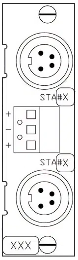
Sensor Part Numbers
Cable Part Numbers
15.5 1F
Description
| Module Part Number | 2-6200-244 |
| Sensor Description | Piezo Diaphragm |
| Gas Dependent | No |
| Module Interface | Amphenol 4 Pin |
| Sensor Interface | Octal Connector |
| Sensor Range (Torr) | 760 to 7600 |
| Calibration Points (Torr) | 760, 7600 |
| Sensors Controlled by Module | 2 |
| MX200 Slots Used | 1 |
| Maximum Modules in Single MX200 | 5 |
Sensor Part Numbers
Cable Part Numbers
15.6 2A
Description
| Module Part Number | 2-6200-486 |
| Sensor Description | Thermocouple |
| Gas Dependent | Yes |
| Module Interface | Amphenol 4 Pin |
| Sensor Interface | Octal Connector |
| Sensor Range (Torr) | 1.0E-3 to 1 |
| Calibration Points (Torr) | 0, 1 |
| Sensors Controlled by Module | 2 |
| MX200 Slots Used | 1 |
| Maximum Modules in Single MX200 | 5 |
Sensor Part Numbers
Cable Part Numbers
15.7 4A
Description
| Module Part Number | 2-6200-415 |
| Sensor Description | Convection |
| Gas Dependent | Yes |
| Module Interface | Amphenol 4 Pin |
| Sensor Interface | Octal Connector |
| Sensor Range (Torr) | 1.0E-3 to 1000 |
| Calibration Points (Torr) | 0, 1, 70, 760 |
| Sensors Controlled by Module | 2 |
| MX200 Slots Used | 1 |
| Maximum Modules in Single MX200 | 5 |
Sensor Part Numbers
Cable Part Numbers
15.8 7B
Description
| Module Part Number | 2-6200-227 |
| Sensor Description | Penning Magnetron Cold Cathode |
| Gas Dependent | Yes |
| Module Interface | MHV |
| Sensor Interface | MHV |
| Sensor Range (Torr) | 1.0E-7 to 1.0E-3 |
| Calibration Points (Torr) | 1.0E-6, 1.0E-5, 1.0E-4, 1.0E-3 |
| Sensors Controlled by Module | 1 |
| MX200 Slots Used | 1.5 |
| Maximum Modules in Single MX200 | 3 |
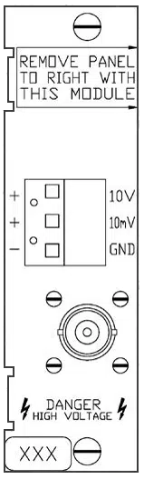
Sensor Part Numbers
Cable Part Numbers
15.9 7E
Description
| Module Part Number | 2-6200-285 |
| Sensor Description | Double Inverted Magnetron Cold Cathode |
| Gas Dependent | Yes |
| Module Interface | SHV5 |
| Sensor Interface | SHV5 |
| Sensor Range (Torr) | 1.0E-8 to 1.0E-2 |
| Calibration Points (Torr) | 1E-5, 1E-3 |
| Sensors Controlled by Module | 1 |
| MX200 Slots Used | 1 |
| Maximum Modules in Single MX200 | 5 |
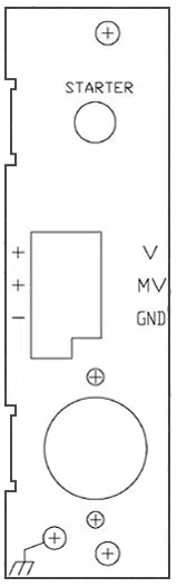
Sensor Part Numbers
Cable Part Numbers
15.10 7F
Description
| Module Part Number | 2-6000-285 |
| Sensor Description | Double Inverted Magnetron Cold Cathode |
| Gas Dependent | Yes |
| Module Interface | SHV5 |
| Sensor Interface | SHV5 |
| Sensor Range (Torr) | 1.0E-11 to 1.0E-2 |
| Calibration Points (Torr) | 1E-5, 1E-3 |
| Sensors Controlled by Module | 1 |
| MX200 Slots Used | 1 |
| Maximum Modules in Single MX200 | 5 |
Sensor Part Numbers
| Description | Part Number | |
| CF40/2.75″ CF-F Stainless Steel | 2-2144-052 | Buy Now |
Cable Part Numbers
15.11 7FC
Description
| Module Part Number | 2-6000-285 |
| Sensor Description | Double Inverted Magnetron Cold Cathode |
| Gas Dependent | Yes |
| Module Interface | SHV5 |
| Sensor Interface | SHV5 |
| Sensor Range (Torr) | 1.0E-11 to 1.0E-2 |
| Calibration Points (Torr) | 1E-5, 1E-3 |
| Sensors Controlled by Module | 1 |
| MX200 Slots Used | 1 |
| Maximum Modules in Single MX200 | 5 |
Sensor Part Numbers
| Description | Part Number | |
| CF40/2.75″ CF-F Stainless Steel | 2-2146-052 | Buy Now |
Cable Part Numbers
15.12 7FCS
Description
| Module Part Number | 2-6000-285 |
| Sensor Description | Double Inverted Magnetron Cold Cathode Quick Start |
| Gas Dependent | Yes |
| Module Interface | SHV5 |
| Sensor Interface | SHV5 |
| Sensor Range (Torr) | 1.0E-11 to 1.0E-2 |
| Calibration Points (Torr) | 1E-5, 1E-3 |
| Sensors Controlled by Module | 1 |
| MX200 Slots Used | 1 |
| Maximum Modules in Single MX200 | 5 |
Sensor Part Numbers
| Description | Part Number | |
| CF25/2.125″ CF-F Stainless Steel | 2-2146-054 | Buy Now |
| CF40/2.75″ CF-F Stainless Steel | 2-2146-053 | Buy Now |
Cable Part Numbers
| Length | Part Number | |
| 7F Triax and 7FCS Quick Start Combination Cable (300′ Max) | 2-9872-000 | Buy Now |
15.13 5A
Description
| Module Part Number | 2-6200-451 (24 V DC) 2-6200-452 (15 V DC) |
| Sensor Description | Capacitance Diaphragm |
| Gas Dependent | No |
| Module Interface | Amphenol 5 Pin |
| Sensor Interface | Sensor Dependent |
| Sensor Range (Torr) | 1E-1 to 1000 |
| Calibration Points (Torr) | 0, Full Scale |
| Sensors Controlled by Module | 2 |
| MX200 Slots Used | 1 |
| Maximum Modules in Single MX200 | 5 |
15.14 5B
Description
| Module Part Number | 2-6200-451 (24 V DC) 2-6200-452 (15 V DC) |
| Sensor Description | Capacitance Diaphragm |
| Gas Dependent | No |
| Module Interface | Amphenol 5 Pin |
| Sensor Interface | Sensor Dependent |
| Sensor Range (Torr) | 1E-2 to 100 |
| Calibration Points (Torr) | 0, Full Scale |
| Sensors Controlled by Module | 2 |
| MX200 Slots Used | 1 |
| Maximum Modules in Single MX200 | 5 |
15.15 5C
Description
| Module Part Number | 2-6200-451 (24 V DC) 2-6200-452 (15 V DC) |
| Sensor Description | Capacitance Diaphragm |
| Gas Dependent | No |
| Module Interface | Amphenol 5 Pin |
| Sensor Interface | Sensor Dependent |
| Sensor Range (Torr) | 1E-3 to 10 |
| Calibration Points (Torr) | 0, Full Scale |
| Sensors Controlled by Module | 2 |
| MX200 Slots Used | 1 |
| Maximum Modules in Single MX200 | 5 |
15.16 5D
Description
| Module Part Number | 2-6200-451 (24 V DC) 2-6200-452 (15 V DC) |
| Sensor Description | Capacitance Diaphragm |
| Gas Dependent | No |
| Module Interface | Amphenol 5 Pin |
| Sensor Interface | Sensor Dependent |
| Sensor Range (Torr) | 1E-4 to 1 |
| Calibration Points (Torr) | 0, Full Scale |
| Sensors Controlled by Module | 2 |
| MX200 Slots Used | 1 |
| Maximum Modules in Single MX200 | 5 |
15.17 5E
Description
| Module Part Number | 2-6200-451 (24 V DC) 2-6200-452 (15 V DC) |
| Sensor Description | Capacitance Diaphragm |
| Gas Dependent | No |
| Module Interface | Amphenol 5 Pin |
| Sensor Interface | Sensor Dependent |
| Sensor Range (Torr) | 1E-5 to 0.1 |
| Calibration Points (Torr) | 0, Full Scale |
| Sensors Controlled by Module | 2 |
| MX200 Slots Used | 1 |
| Maximum Modules in Single MX200 | 5 |
15.18 5F
Description
| Module Part Number | 2-6200-451 (24 V DC) 2-6200-452 (15 V DC) |
| Sensor Description | Capacitance Diaphragm |
| Gas Dependent | No |
| Module Interface | Amphenol 5 Pin |
| Sensor Interface | Sensor Dependent |
| Sensor Range (Torr) | Custom |
| Calibration Points (Torr) | 0, Full Scale |
| Sensors Controlled by Module | 2 |
| MX200 Slots Used | 1 |
| Maximum Modules in Single MX200 | 5 |
15.19 Set Point Relay
The set point relay module includes 4 relays for use with set points. The electrical connections to the relays are accessed through (4) 3 position screw terminals on the module. This module uses 1 slot in the MX200 and a maximum of 2 modules can be used in a single MX200, providing up to 8 set point relays. For additional information on set points, see Section 13.
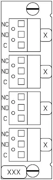
15.20 Power Supply Module
The power supply module includes a power switch, a connection for 110 V AC/220 V AC power, and a voltage selection switch. Be sure that the voltage selection switch is in the correct position for your system before turning on the unit.
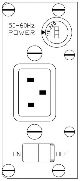
15.21 RS-232/RS-485/USB Communications Module and Lockout Switch
The RS-232/RS-485/USB communications module includes a D-sub 9-pin female connection for RS-232, a 3-position screw terminal connection for RS-485, and a USB B-type receptacle for USB. There is also a lockout switch, which is described in more detail below, and a hard reset button, described in more detail in Section 20.3. The communications module must be connected to slot 7. Additionally, the standard MX200 will include the communications module. It is not an optional component.
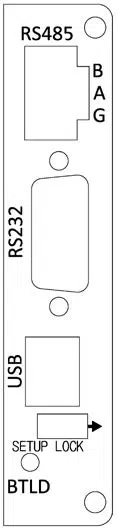
15.22 Industrial Ethernet Communications Module and Lockout Switch
Two industrial ethernet communications modules are available: EthernetIP and PROFINET. The information in this section applies to both modules.
The industrial ethernet communications modules include two RJ45 ethernet port connections and a USB B-type receptacle for USB. There is also a lockout switch, which is described in more detail below, and a hard reset button, described in more detail in Section 20.3.
The industrial ethernet communication module must be connected to slots 6 and 7. It is not an optional component.
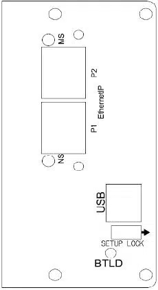
USB Cable
| Length | Part Number |
| 1.8 m (6 ft) | 1-2400-005 |
The setup lock switch prevents changes to any of the settings through the front panel when the switch is set in the direction of the arrow. Note that digital communications (such as USB, RS-232, or RS-485) can still be used to change the unit settings.
15.23 Additional Notes on Modules, Sensors, and Cables
Radiation resistant and high temperature cables are available for many sensors. Refer to specific sensor data sheets for more information.
The MX200 does not currently control any hot ion sensors.
16. High Vacuum Measurement
16.1 Description
Cold cathodes provide high vacuum measurement and these sensors cannot remain energized at pressures above 1.0E-2 Torr. They therefore must be switched on and off manually or by using another Televac® low vacuum sensor. If the cold cathode is energized at pressures above 1.0E-3 Torr for extended periods of time, particularly in environments where oxygen is present, rapid degradation of the sensor will occur due to contamination from sputtering of the cathode.
16.2 Changing Between Auto and Manual Modes
To change the cold cathodes between auto and manual modes, press the home button then navigate through the following menus:
Global Setup > Cold Cathode
Scroll to the “Mode: Auto/Manual” line and press the ENT button to switch between the two options. This can also be accomplished through digital communications, see Section 9 for more information.
16.3 Manual High Vacuum Switching
Manual high vacuum switching is accomplished by pressing the home button then navigating through the following menus:
Global Setup > Cold Cathode
Scroll to the “Even Status: On/Off” or “Odd Status: On/Off” line and press the ENT button to toggle the status of the selected channels. Note that if the cold cathode is transitioning from high vacuum to low vacuum and reaches a pressure above 1.0E-2 Torr, it will go into overcurrent and automatically power off to prevent damage to the sensor.
16.4 Automatic High Vacuum Switching
Cold cathode sensors can be automatically switched on and off by Televac® low vacuum sensors. When in automatic mode, the lowest channel with a low vacuum sensor will control the odd or even channel above it. For example, a low vacuum sensor connected to channel 1 will control cold cathode sensors connected to channels 3, 5, 7, and 9. A low vacuum sensor connected to channel 2 will control cold cathode sensors connected to channel 4, 6, and 8.
16.5 Additional Notes
Cold cathode sensors cannot be connected to channel 10.
If a cold cathode sensor is connected to channel 1 or 2 it cannot be automatically controlled by a low vacuum sensor.
The MX200 will not control any hot ion sensors.
17. Cleaning Sensors
17.1 Description
Sensors will become contaminated over time when they are used, leading to decreased accuracy. Contamination is used here as a general term for a variety of conditions including, but not limited to, oxidation and deposited materials on the internal portions of the sensor.
In many situations, this contamination can be cleaned from the sensor to restore it to normal operation. Sensors must be removed from your vacuum system before cleaning; be sure to adhere to all safety procedures related to removing the sensors from your system. Note that the 1E and 1F piezo diaphragm sensors cannot be cleaned. CDGs must be returned to their manufacturer for service.
If the sensor is still providing inaccurate readings after cleaning, the anode assembly (for cold cathodes) or the entire sensor may need to be replaced, or the MX200 controller may need to be re-calibrated with the sensor.
17.2 2A and 4A Thermocouple and Convection Cleaning
2A thermocouple and 4A convection enhanced thermocouple sensors can be rinsed with acetone or methanol. Note that these sensors utilize internal filaments to make vacuum measurements. It is important that the geometry of these filaments is maintained to provide the most accurate readings. Care must, therefore, be taken during the rinsing process to prevent any changes to the filament geometry.
Ensure that the sensors are dry before re-installing them on your system to prevent the introduction of any unintended substances.
17.3 General Information on Cold Cathode Cleaning
We suggest bead blasting for all cold cathodes except the 7FC and 7FCS, but a fine grade Scotch-Brite pad can be used when bead blasting is unavailable. We strongly recommend against using steel wool to clean cold cathodes. Steel wool can create small magnetic particles, permanently damaging the sensor when turned on.
17.4 7B Cold Cathode Cleaning
Refer to the following cross-sectional diagram while cleaning the 7B sensor:
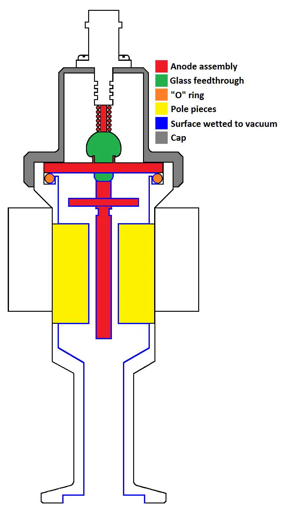
Cleaning Steps
- Remove the cap by unscrewing it (labeled with gray in the diagram).
- Pull the anode assembly out of the body (labeled with red in the diagram).
- Remove the “O” ring from the body of the sensor, taking care not to scratch the “O” ring seat (labeled with orange in the diagram).
- Wipe off the “O” ring with a lint free wipe.
- Visually inspect the “O” ring for cracks or tears, it should also be round and not flattened. If any physical defects are found, the “O” ring should be replaced.
- Blast the vacuum wetted portions of the anode assembly at 30 PSI using 70 to 140 mesh glass beads (labeled with red and blue in the diagram). Be careful not to damage the glass feedthrough at the base of the assembly (labeled with green in the diagram). If a rainbow effect is noticed on the glass feedthrough, a crack may exist and the anode assembly should be replaced. See below for relevant part numbers.
- Blast the vacuum wetted portions of the body with glass beads (labeled with blue in the diagram), concentrating on the pole piece and “O” ring areas, but making sure to clean all surfaces wetted to vacuum. If the threaded end of the tube needs to be cleaned, it can be bead blasted as well.
- After cleaning, use compressed dry air to remove any residual glass beads or dust from the sensor.
- Ensure that there are no loose metal particles around the pole pieces.
- Grease the “O” ring with Apiezon L or M Grease (a vacuum approved grease). The “O” ring should be shiny, be sure not to apply excess grease.
- Install the “O” ring in the body.
- Install the anode assembly in the body; observe the keyway location.
- Replace the cap and hand tighten it.
- Reinstall the sensor on the vacuum chamber.
- Allow several hours for the sensor to degas when your system is pumped down to high vacuum.
- If properly cleaned and assembled, the sensor is ready for use without re-calibration unless ISO 17025 accredited or NIST traceable calibration is required.
Anode Assembly Part Numbers
| Description | Part Number | |
| 7B Anode Assembly | 2-6200-37 | Buy Now |
| O-Ring | 1-4210-50 | Buy Now |
| Red Cap | 6-4210-25 | Buy Now |
17.5 7E Cold Cathode Cleaning
Refer to the following cross-sectional diagram while cleaning the 7E sensor:
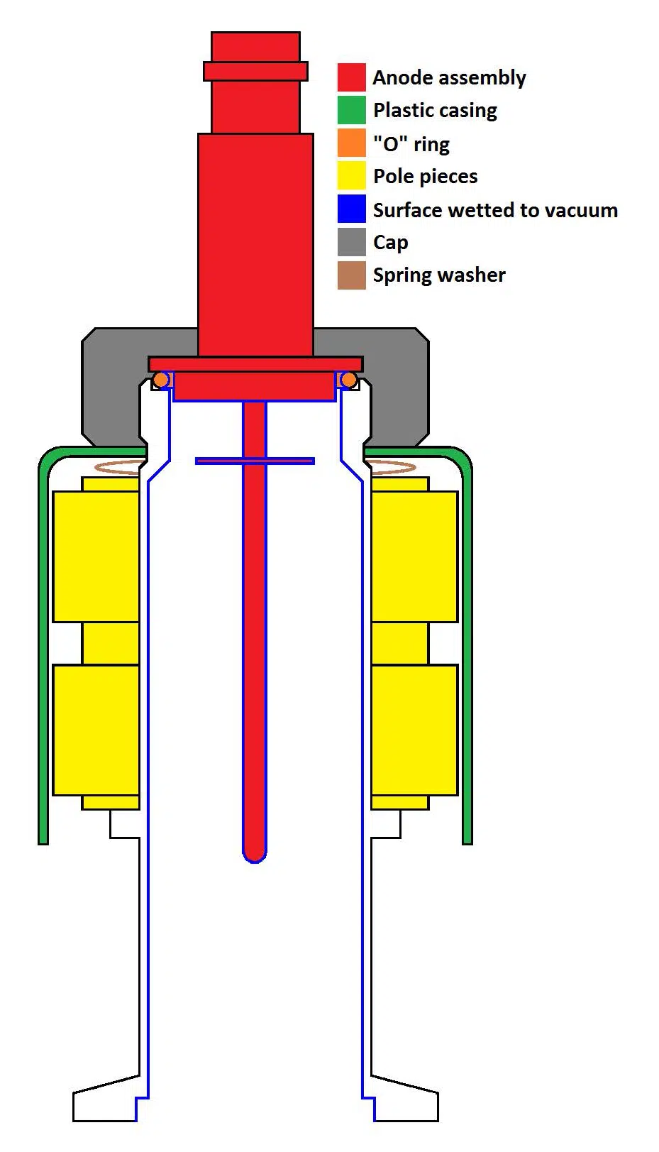
Cleaning Steps
- Remove the cap by unscrewing it (labeled with gray in the diagram).
- Remove the plastic casing (labeled with green in the diagram).
- Remove the spring washer (labeled with brown in the diagram).
- Pull the anode assembly out of the body (labeled with red in the diagram).
- Remove the magnet assembly from the body (labeled with yellow in the diagram).
- Remove the “O” ring from the body of the sensor, taking care not to scratch the “O” ring seat (labeled with orange in the diagram).
- Wipe off the “O” ring with a lint free wipe.
- Visually inspect the “O” ring for cracks or tears, it should also be round and not flattened. If any physical defects are found, the “O” ring should be replaced.
- Blast the vacuum wetted portions of the anode assembly at 30 PSI using 70 to 140 mesh glass beads (labeled with red and blue in the diagram). Be careful not to damage the glass feedthrough at the base of the assembly. If a rainbow effect is noticed on the glass feedthrough, a crack may exist and the anode assembly should be replaced. See below for relevant part numbers.
- Blast the vacuum wetted portions of the body with glass beads (labeled with blue in the diagram), concentrating on the areas surrounding the anode assembly, but making sure to clean all surfaces wetted to vacuum. If the threaded end of the tube needs to be cleaned, it can be bead blasted as well.
- After cleaning, use compressed dry air to remove any residual glass beads or dust from the sensor.
- Ensure that there are no loose metal particles around the pole pieces.
- Grease the “O” ring with Apiezon L or M Grease (a vacuum approved grease). The “O” ring should be shiny, be sure not to apply excess grease.
- Install the “O” ring in the body.
- Install the magnet assembly on the body.
- Install the spring washer on the body.
- Install the anode assembly in the body; observe the keyway location.
- Replace the plastic casing.
- Replace the cap and hand tighten it.
- Reinstall the sensor on the vacuum chamber.
- Allow several hours for the sensor to degas when your system is pumped down to high vacuum.
- If properly cleaned and assembled, the sensor is ready for use without re-calibration unless ISO 17025 accredited or NIST traceable calibration is required.
Anode Assembly Part Numbers
| Description | Part Number | |
| 7E Anode Assembly | 2-7900-075 | Buy Now |
| O-Ring | 6-4210-260 | Buy Now |
17.6 7FC and 7FCS Cold Cathode Cleaning
Refer to the following cross-sectional diagram while cleaning the 7FC and 7FCS sensors. Note that the thermionic emitter is only included with the 7FCS.
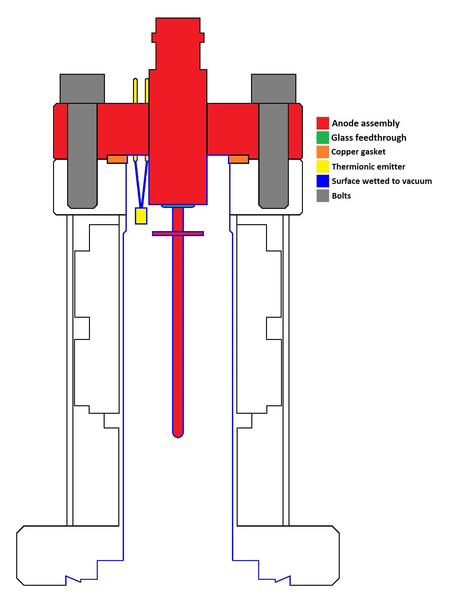
Cleaning Steps
- Unscrew the 4 bolts from the top of the sensor (labeled with gray in the diagram).
- Pull the anode assembly out of the body (labeled with red in the diagram).
- Remove the copper gasket from the body of the sensor. Note that copper gaskets are one time use and should be replaced every time the sensor is disassembled.
- Use a fine grade Scotch-Brite pad to clean the vacuum wetted portions of the anode assembly (with the exception of the thermionic emitter on the 7FCS). If a rainbow effect is noticed on the glass feedthrough, a crack may exist and the anode assembly should be replaced. See below for relevant part numbers. Take care not to damage the thermionic emitter on the 7FCS while cleaning.
- Blast the vacuum wetted portions of the body with glass beads (labeled with blue in the diagram), concentrating on the areas surrounding the anode assembly, but making sure to clean all surfaces wetted to vacuum.
- After cleaning, use compressed dry air to remove any residual glass beads or dust from the sensor.
- Ensure that there are no loose metal particles attached to the inner body of the sensor.
- Install a new copper gasket in the body.
- Install the anode assembly in the body; observe the keyway location.
- Replace the bolts and tighten them.
- Reinstall the sensor on the vacuum chamber.
- Allow several hours for the sensor to degas when your system is pumped down to high vacuum.
- If properly cleaned and assembled, the sensor is ready for use without re-calibration unless ISO 17025 accredited or NIST traceable calibration is required.
18. Understanding Cold Cathodes
18.1 Description
Cold cathodes provide indirect high vacuum measurement by ionizing gas molecules present in the vacuum chamber. Televac® offers two types of cold cathodes; Penning (called the 7B) and double inverted magnetron (called the 7E, 7F, 7FC, and 7FCS).
Both types of cold cathodes have similar operating principles with a high voltage of 2 kV to 4 kV present between the anode and cathode, a magnet assembly to create a magnetic field in the ionization chamber, and utilization of current measurement to measure the pressure in the vacuum chamber.
Cold cathodes should not remain energized at pressures above 1.0E-2 Torr, and should not be maintained at pressures above 1.0E-3 for extended periods of time. If the cold cathode is energized at pressures above 1.0E-3 Torr for extended periods of time, particularly in environments where oxygen is present, rapid degradation of the sensor will occur due to contamination from sputtering of the cathode.
19. Capacitance Diaphragm Gauges (CDGs)
19.1 Description
Televac® does not manufacture capacitance diaphragm gauges, but we do offer a module for the MX200 to interface with them. This allows the user to display readings from CDGs on the front panel of the MX200 and to output their values through analog 0 to 10 V DC outputs or digital communications. The MX200 can interface with any CDG from MKS Instruments, Inc. provided that it is a supported range (0.1, 1, 10, 100, or 1000 Torr full scale range) and that it draws less than 250 mA of current at 15 V DC.
20. Firmware Upgrades and the Bootloader
20.1 Description
The bootloader allows the user to upgrade the MX200 logic and display software from a computer through a serial communications program. Firmware upgrades must be completed through the USB connection on the communications module of the unit; other communication methods are not currently supported. These instructions assume the use of a Windows PC with Tera Term to upload the new version of the firmware.
20.2 Upgrading the Firmware
Download the updated version of the logic or display software to your computer.
Establish communications with the MX200 by following Televac® Application Note 3008.
To enter the logic bootloader, send the following command and wait for the MX200 to enter the bootloader:
[USER TX] PG_LGC<cr>
[USER RX] Bootloader MX200 Logic VX.X<cr>
[USER RX] Waiting for download…<cr>
To enter the display bootloader, send the following command and wait for the MX200 to enter the bootloader:
[USER TX] PG_DSP<cr>
[USER RX] Bootloader MX200 Display VX.X<cr>
[USER RX] Waiting for download…<cr>
Ensure that Tera Term is configured for 57600 baud rate and Xon/Xoff flow control by viewing the settings in Setup > Serial port…
In Tera Term, go to File > Send file… then point to the update file that you downloaded.
Wait for Tera Term to complete the file transfer, note that this can take up to several minutes. Do not disconnect the MX200 from your computer or power down the MX200 or your computer during this process.
When the file transfer is complete, power cycle the MX200.
Your MX200 is now updated, enjoy!
20.3 Hardware Bootloader
If an error ever occurs during a software upgrade or if the bootloader is non-responsive, take the following steps to enter the bootloader with a hard reset:
Power down the MX200.
Locate the button on the communications module labeled BTLD.
Hold down the button and turn on the MX200. Continue holding down the button while the MX200 powers up for at least 3 seconds.
Follow the steps in Section 20.2 to restore the MX200 firmware.
21. Software Versioning
21.1 Description
The software version is a 6 digit number displayed during startup. It can be viewed with more detailed information once the unit has started by pressing the home key and selecting the Version Information at the bottom of the screen. Please have this information ready when you contact Televac® with any questions about your unit.
22. Certifications
22.1 CE
EN61326-1:2006
22.2 UL
UL61010-1
22.3 RoHS
The logic, display, power supply, and communication modules are compliant with the Restriction of Hazardous Substances Directive 2002/95/EC (RoHS). Sensor modules are not RoHS compliant.
The EthernetIP and PROFINET communication modules are compliant with the Restriction of Hazardous Substances Directive 2002/95/EC (RoHS).
22.4 REACH
Compliant
23. Troubleshooting
23.1 Cold Cathode Switching
Question: I’m using a rough vacuum sensor to automatically turn on my cold cathode. When the cold cathode turns on, it immediately jumps to a very low pressure reading that I know is incorrect. Why is this happening?
Answer: What’s happening is that the cold cathode isn’t starting properly, so it’s reading zero current and the MX200 translates this to very low pressure. If the system is left for several minutes (up to 30 in extreme situations) the cold cathode will likely start and read a correct pressure. There are several reasons why this can happen, below are several suggestions for resolving the issue.
Resolution 1: Over time, rough vacuum sensors become contaminated from use. This typically causes the zero to drift up, which means that the cold cathode is turned on when the system is at a pressure where the cold cathode cannot turn on or “start”. Recalibrating the rough vacuum sensor zero (see Section 14) or replacing it will resolve the issue. If the sensor is replaced, it should also be recalibrated.
As an example, the standard turn on point for the cold cathode is when the rough vacuum sensor reaches 1.0E-2 Torr (10 mTorr, mTorr is equivalent to microns). If the rough sensor zero has drifted up from contamination, it could be reading 1.0E-2 Torr when the system is actually at 1.0E-4 Torr (0.1 mTorr). If the cold cathode is turned on at this pressure, it most likely will not start properly and will jump to a very low pressure reading.
Resolution 2: Contamination of the cold cathode can cause this behavior. Try disassembling and cleaning sensor and re-installing it on your system. Cleaning instructions for cold cathodes can be found in Section 17. Remember to power down the MX200 and disconnect power before performing this service.
Resolution 3: If you have a new system where this is occurring, it’s possible the behavior is caused by the pumping speed. In this situation, the rough vacuum sensor isn’t reacting quickly enough and again the cold cathode is turned on at a pressure where it can’t start. Try slowing down the pumping speed, changing the cold cathode port diameter, or moving the cold cathode to a location further from the pump.
Resolution 4: A damaged cold cathode cable can also cause this behavior. Try replacing the cable or contacting Televac® for details about the cable to test its continuity. Remember to power down the MX200 and disconnect power before performing this service.
Resolution 5: A problem with the cold cathode module can cause this behavior. You can purchase a new module and replace it yourself (be sure to note the cold cathode model before purchasing a new module) or return the unit to Televac® for service. Remember to power down the MX200 and disconnect power if you perform this service yourself.
Resolution 6: Contact Televac® for an RMA. We are happy to evaluate the MX200 if you would like to return it to us. It’s best if you can return the unit with all of the sensors and cables, but we understand this isn’t always possible.
24. Vacuum Measurement Unit Conversions
24.1 Converting Between Torr Scientific, Torr Decimal, mTorr, and Microns
| Torr Scientific | Torr Decimal | mTorr/Microns |
| 1.0E-03 | 0.001 | 1 |
| 2.0E-03 | 0.002 | 2 |
| 3.0E-03 | 0.003 | 3 |
| 4.0E-03 | 0.004 | 4 |
| 5.0E-03 | 0.005 | 5 |
| 6.0E-03 | 0.006 | 6 |
| 7.0E-03 | 0.007 | 7 |
| 8.0E-03 | 0.008 | 8 |
| 9.0E-03 | 0.009 | 9 |
| 1.0E-02 | 0.010 | 10 |
| 2.0E-02 | 0.020 | 20 |
| 3.0E-02 | 0.030 | 30 |
| 4.0E-02 | 0.040 | 40 |
| 5.0E-02 | 0.050 | 50 |
| 6.0E-02 | 0.060 | 60 |
| 7.0E-02 | 0.070 | 70 |
| 8.0E-02 | 0.080 | 80 |
| 9.0E-02 | 0.090 | 90 |
| 1.0E-01 | 0.100 | 100 |
| 2.0E-01 | 0.200 | 200 |
| 3.0E-01 | 0.300 | 300 |
| 4.0E-01 | 0.400 | 400 |
| 5.0E-01 | 0.500 | 500 |
| 6.0E-01 | 0.600 | 600 |
| 7.0E-01 | 0.700 | 700 |
| 8.0E-01 | 0.800 | 800 |
| 9.0E-01 | 0.900 | 900 |
| 1.0E+00 | 1 | 1000 |
| 2.0E+00 | 2 | 2000 |
| 3.0E+00 | 3 | 3000 |
| 4.0E+00 | 4 | 4000 |
| 5.0E+00 | 5 | 5000 |
| 6.0E+00 | 6 | 6000 |
| 7.0E+00 | 7 | 7000 |
| 8.0E+00 | 8 | 8000 |
| 9.0E+00 | 9 | 9000 |
| 1.0E+01 | 10 | 10,000 |
| 2.0E+01 | 20 | 20,000 |
| 3.0E+01 | 30 | 30,000 |
| 4.0E+01 | 40 | 40,000 |
| 5.0E+01 | 50 | 50,000 |
| 6.0E+01 | 60 | 60,000 |
| 7.0E+01 | 70 | 70,000 |
| 8.0E+01 | 80 | 80,000 |
| 9.0E+01 | 90 | 90,000 |
| 1.0E+02 | 100 | 100,000 |
| 2.0E+02 | 200 | 200,000 |
| 3.0E+02 | 300 | 300,000 |
| 4.0E+02 | 400 | 400,000 |
| 5.0E+02 | 500 | 500,000 |
| 6.0E+02 | 600 | 600,000 |
| 7.0E+02 | 700 | 700,000 |
| 8.0E+02 | 800 | 800,000 |
| 9.0E+02 | 900 | 900,000 |
| 1.00E+03 | 1000 | 1,000,000 |