


1 Introduction
1.1 Disclaimer
All information in this manual is subject to change without notice. The Fredericks Company assumes no responsibility for inaccuracies in product specifications or any liability arising from product use. Please contact Televac® by visiting our website, or calling +1 215 947 2500 with comments or questions.
1.2 Description
The MX7M is a cold cathode ionization gauge with a measurement range of 5*10-11 Torr to 1*10-2 Torr. It utilizes a Televac®> cold cathode ionization sensor in the inverted magnetron configuration with part numbers 2-8950-KF25 (KF25 flange version), 2-8950-KF40 (KF40 flange version), 2-8950-KF16 (KF16 flange version) or 2-8950-CF40 (CF40 flange version). It has a two-color OLED display with selectable units of Torr, Millibar, and Kilopascal. Settings can be changed through RS-485 communications with a PC, through USB communications with a PC, or through the unit’s front panel using four capacitive touch buttons located on the top of the unit. The MX7M has two set points, one relay and one open collector, and a selectable analog output option. The analog output is a configurable 0-10 V output that includes options for linear, linear-by-decade, and logarithmic formats.
1.3 Operating Specifications
| Operating Range | 5*10-11 Torr to 1*10-2 Torr |
| Communications | RS-485 and USB |
| Programmable Set Points | 2 |
| Set Point 1 | Open Collector |
| Set Point 2 | Relay |
| Analog Output | Configurable 0 to 10 V DC |
| Supply Voltage | +22 to +26 V DC |
| Maximum Power | 8 W |
| Calibration Medium | Dry air or nitrogen |
| Overpressure | 150 PSI |
| Digital Output Resolution | 2 significant digits with exponent |
| Analog Output Resolution | 16 bits |
| Operating Temperature | 0 °C to 50 °C |
| Storage Temperature | -20 °C to 60 °C |
| Bakeout Temperature | 250 °C (electronics removed) |
| Response Time | ≤ 1 second |
| Accuracy | |
| 1*10-9 to 1*10-3 Torr | ±30% |
| Analog Output | ±10 mV |
| Display Readable Distance | 3 m (10 ft) |
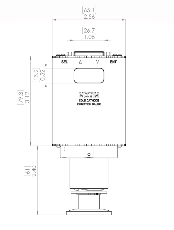
1.4 Dimensions
2. Safety Information
2.1 General Safety Information
In these instructions, the word “product” refers to the MX7M and all of its approved parts and accessories. NOTE: These instructions do not and cannot provide for every contingency that may arise in connection with the installation, operation, or maintenance of this product. Should you require further assistance, please contact Televac® by visiting our website at or calling +1 215 947 2500 with comments or questions..
This product has been designed and tested to offer reasonably safe service provided in it is installed, operated and serviced in strict accordance with these safety instructions.
These safety precautions must be observed during all phases of operation, installation, and service of this product. Failure to comply with these precautions or with specific warnings elsewhere in this manual violates safety standards of design, manufacture, and intended use of the instrument. Televac® disclaims all liability for the customer’s failure to comply with these requirements.
- Read instructions – Read all safety and operating instructions before operating the product.
- Retain instructions – Retain the safety and operating instructions for future reference.
- Heed warnings – Adhere to all warnings on the product and in the operating instructions.
- Follow instructions – Follow all operating and maintenance instructions.
- Accessories – Do not use accessories not recommended in this manual as they may require a technician to restore the product to its normal operation.
The MX7M has voltages up to 4500 volts. As such, it represents a shock hazard and should be handled with caution. Any disassembly of the gauge should be carried out by a trained professional and with the power disconnected.
Do not substitute parts or modify instrument. Because of the danger of introducing additional hazards, do not install substitute parts or perform any unauthorized modifications to the product. Return the product to Televac® for service and repair to ensure that safety features are maintained. Do not use this product if it has unauthorized modifications.
3. Quick Start Guide
3.1 Check What You’ve Received
Compare what you’ve received to your purchase order.
3.2 Safety Instructions
Review all safety instructions outlined in Section 2.
3.3 Connect Power
Connect a 24V power supply to the unit. See the pin out in Section 4.2 for more information.
3.4 Check the Measurement Screen
The unit should power up and display “OFF” on the measurement screen. Do not attempt to turn on the high voltage.
3.5 Power Down the MX7M
Power down the MX7M, and install it on a vacuum stand for use.
4. Setup
4.1 Installation
Each MX7M is designed to be used in conjunction with a 7M sensor. The 7M sensor can be mounted in any position however it is recommended to mount it away from any contaminants that might be in the system as over time this can affect the measurement accuracy. Mounting the 7M sensor close to the area where vacuum measurement is desired is preferred to increase the accuracy. Each 7M sensor has a key that only allows for the MX7M to mate with the sensor in the proper orientation. Rotate the MX7M until the correct alignment is obtained and the MX7M is able to slide onto the 7M sensor. Connect the power connector to the top of the unit and be sure to tighten the screws so that a firm connection is maintained.
Try to avoid connecting the MX7M to the vacuum chamber by long or narrow piping as this may affect the accuracy and response time of the unit. Avoid mounting the unit near a heater within the chamber as this may affect the measurement accuracy. Excessive vibration of the unit may affect accuracy and decrease the life of the unit. Exposure to oils and other contaminants will decrease the accuracy and decrease the life of the sensor. Do not expose the unit to corrosive gases.
4.2 Electrical Information
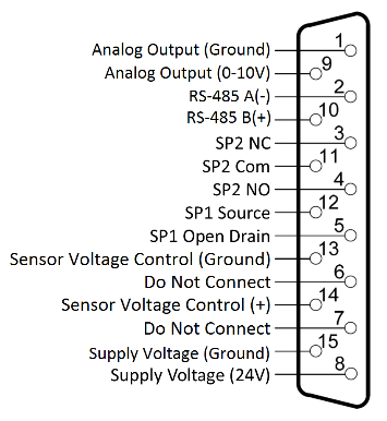
Power connectors and adapters for use with the MX7M are available for purchase from Televac®. Operators wishing to create their own adapters should refer to the pin out of the MX7M below. Each connection labeled “Floating” has no connection and should remain so.
| Pin | Description |
| 1 | Analog Output (Ground) |
| 2 | RS-485 (-) |
| 3 | SP2 NC |
| 4 | SP2 NO |
| 5 | SP1 Open Drain |
| 6 | Do Not Connect |
| 7 | Do Not Connect |
| 8 | Supply Voltage |
| 9 | Analog Output (0 to 10 V) |
| 10 | RS-485 B(+) |
| 11 | SP2 Com |
| 12 | SP1 Source |
| 13 | Sensor Voltage Control |
| 14 | Sensor Voltage Control |
| 15 | Supply Voltage (Ground) |
4.3 Turning the High Voltage On and Off
The MX7M has an operating range that does not include measurement above 1*10-2 Torr. If the unit is operated above 1*10-2 Torr, the sensor will be damaged and electrical arcing inside the sensor may occur. To prevent this, the unit should be paired with a low vacuum gauge, such as the MX4A or MX2A, to ensure safe operation.
The MX7M provides two control methods for toggling the high voltage; Menu Control and Pin Control. To select which method is used, navigate to the Vsense Control menu screen and select either Menu or Pins. Pin Control is provided through pins 13 and 14 of the MX7M connector.
To turn on the sensor when Menu Control is selected, use one of the following two options: from the Measurement Screen, press SEL to navigate to the Vsense Control, then press ENT to unlock the control, press UP to toggle the status to ON, and then press ENT to save the change. The high voltage should now turn on. In Menu Control mode, the high voltage can also be toggled by sending the appropriate command to turn on the sensor through RS-485 or USB Communications. To turn off the sensor in Menu Control mode, navigate to the Vsense Control screen, press ENT to unlock the menu, press UP to toggle the status to OFF, and press ENT to save the change. Alternatively, when in Menu Control mode, the user may send the appropriate command to turn off the sensor through RS-485 or USB Communications.
To turn on the sensor when Hardware Control is selected, short pins 13 and 14 together. To turn off the sensor, open the path between pins 13 and 14. This functionality is included to easily interface with a low vacuum gauge, such as the Televac® MX2A or MX4A, to automatically control the unit via an open collector or relay. For more information see Application Note AN 3023.
To protect the sensor from damage, if the sensor high voltage is toggled on when in either Menu Control or Pin Control mode the pressure is above 1*10-2 Torr, overcurrent protection will turn the sensor off. If the sensor is in Menu Control mode, then a command to turn on the sensor will need to be sent via communication or through the front panel to toggle the high voltage on again. If Pin Control is enabled, then the unit will attempt every to turn the high voltage on every 60 seconds until overcurrent protection does not occur.
7. Analog Output
7.1 Description
The MX7M provides the option for outputting the pressure reading in an analog form. Operators who wish to use PLCs to monitor processes should find this function useful. There are three different analog output formats to choose between. The formats include Logarithmic, Linear by Decade, and Linear.
7.2 Linear
The Linear output covers a select range of the MX7M with a linear scale. The 10 Volt or full-scale value of the output can be selected from the following values: 1*10-5 Torr, 1*10-4 Torr, or 1*10-3 Torr. The scale extends three decades below the full-scale value. Three decades below the 10 V value is the 0 V value. This corresponds to the low end of the range and output below the 0 V value is not available. For a wider range use a different analog output format. Note that only the 10 V exponent is selectable. When navigating through the menu, the 0 V exponent will be viewable but not settable. Use the high value (1.0*10H) exponent H in the following equation to convert the voltage output to pressure:
Voltage Output x 10H-1 = Pressure Output
To select the Linear output, navigate to the Analog Output screen, press ENT, and then use the UP or DOWN arrow to select Linear. Press ENT to save the change. Then press DOWN once to navigate to the Output High screen. Press ENT to unlock the screen and press UP or DOWN to select the full-scale pressure for the analog output.
7.3 Linear by Decade
The Linear by Decade output spans the entire range of the MX7M. It uses the units digit of the voltage reading to communicate the decade of the pressure reading and the units after the decimal to communicate the specific pressure using the very generalized expression below, where A, B, C, and D are digits ranging from 0-9:
Voltage = A. BCD → Pressure(Torr) = 10A-11 * .BCD
For example, a voltage reading of 8.367 Volts corresponds to a pressure of 3.67*10-4 Torr.
108-11 * .367 – 10-3 * .367 * 10-4 Torr
To select the Linear by Decade output, navigate to the Analog Output screen, press ENT, and then use the UP or DOWN arrow to select Linear by Decade. Press ENT to save the change.
7.4 Logarithmic
The Logarithmic output covers the entire range of the MX7M, or can be used with a selected range. To use this output, the user must select an exponent that corresponds to 10 V DC and the exponent that corresponds to 0 V DC. The exponent chosen for this format uses the formula below to convert the output voltage into a pressure measurement. Note that H is the exponent of the 10 V value and L is the exponent of the 0 V DC value. “Voltage” is the analog output voltage.
Span =
10
H − L
Offset = 0 − L
Pressure (Torr) = 10
(
Volt
Span
− Offset)
For example, with the logarithmic range set to a 0 V value of 1*10-7 and a 10 V value of 1*10-3 and a voltage reading of 3.075 Volts, the pressure corresponds to:
Span =
10
−3 − (−7)
= 2.5
Offset = 0 − ( − 7 ) = 7
Pressure (Torr) = 10
(
3.075
2.5
− 7)
= 1.7*10−6 Torr
To select the Logarithmic output, navigate to the Analog Output screen, press ENT, and then use the UP or DOWN arrow to select Logarithmic option. Press ENT to save the change. Press the DOWN arrow to navigate to the 10 V DC exponent selection screen. Press ENT to unlock and then the UP or DOWN arrow to select the value. Press ENT to save the value. Press the DOWN arrow to navigate to the 0 V DC exponent selection screen. Press ENT to unlock the screen and the UP or DOWN arrow to select the 0 V DC value.
7.5 Logarithmic 2
The Logarithmic 2 output covers the entire range of the MX7M, or can be used with a selected range. To use this output, the user must select an exponent that corresponds to 10.0 V DC and the exponent that corresponds to 1.0 V DC. The exponent chosen for this format uses the formula below to convert the output voltage into a pressure measurement. Note that H is the exponent of the 10.0 V DC value and L is the exponent of the 1.0 V DC value. “Voltage” is the analog output voltage. Any values below 5*10-11 Torr will output 1.0 V DC.
Span =
H − L
9
Pressure(Torr) = 10(span * (voltage – 1 )) + L
For example, with the logarithmic range set to a 1.0 V DC value of 1*10-11 and a 10.0 V DC value of 1*10-2 and a voltage reading of 3.100 V DC, the pressure corresponds to:
Span =
− 2 − (−11)
9
= 1
Pressure (Torr) = 10(1 * (3.100 -1)) + (−11) = 1.3 * 10−9 Torr
To select the Logarithmic 2 output, navigate to the Analog Output screen, press ENT, and then use the UP or DOWN arrow to select Logarithmic 2 option. Press ENT to save the change. Press the DOWN arrow to navigate to the 10 V DC exponent selection screen. Press ENT to unlock and then the UP or DOWN arrow to select the value. Press ENT to save the value. Press the DOWN arrow to navigate to the 1 V DC exponent selection screen. Press ENT to unlock the screen and the UP or DOWN arrow to select the 1 V DC value.
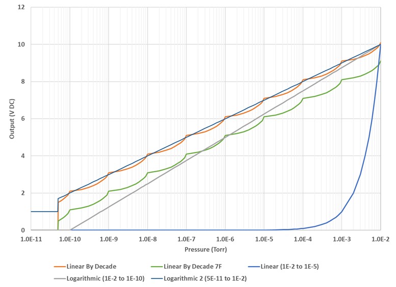
Selected analog output graphs for different scaling and high and low values are shown below:
8. Cleaning the MX7B Sensor
8.1 Cleaning Instructions
- Remove the sensor from the electronics assembly by loosening the two set screws in the base of the electronics. A .050” Allen wrench is necessary for this step.
- Remove the six bolts from the top of the unit. These require a 7/64 Allen wrench.
- The MX7M ships by default with a copper gasket to allow customers to use the full range of the MX7M. Any standard CF16 gasket will work with the MX7M. Once the bolts are removed, the used copper gasket can be pulled free and discarded. Be sure not to scratch the knife-edge surface.
- If the gasket has been replaced with an O-ring, handle the O-ring gently and wash with isopropyl alcohol, methanol, or DI water. Wipe with a lint-free cloth.
- Wipe the inside of the tube with scotch-brite or similar. Do not use steel wool due to the magnets present in the sensor.
- If wiping the inside of the tube does not remove all build up, bead blast the vacuum wetted portions of the anode assembly at 30 PSI using 70 to 140 mesh glass beads (labeled with red and blue in the diagram). Be careful not to damage the knife edge of the sensor.
- Blast the vacuum wetted portions of the body with glass beads (labeled with blue in the diagram), concentrating on the pole piece and “O” ring areas, but making sure to clean all surfaces wetted to vacuum. If the threaded end of the tube needs to be cleaned, it can be bead blasted as well.
- After cleaning, use compressed dry nitrogen to remove any residual glass beads or dust from the sensor.
- Wipe the anode with scotch-brite or similar. Blow with compressed dry nitrogen.
- Install a new gasket or cleaned O-ring and seat the anode.
- Before replacing the bolts, observe the keyway locations line up between the anode and the body.
- Replace bolts and tighten.
- Insert sensor into the electronics and tighten the set screws.
- Reinstall the sensor on the vacuum chamber.
- Allow several hours for the sensor to degas when your system is pumped down to high vacuum.
- If properly cleaned and assembled, the sensor is ready for use without re-calibration unless ISO 17025 accredited or NIST-traceable calibration is required.
| Description | Part Number |
| MX7M Anode Assembly | 1-7900-011 |
| MX7M Electronics Assembly | 2-8950-000 |
| DN16 Copper Gasket | 6-4200-031 |
| DN16 Viton O-Ring | 6-4200-030 |

9. RS-485 and USB Communications
9.1 Description
This gauge communicates with the host computer through an RS-485 or USB interface. Each communication correspondence consists of a command line sent by the host computer and a response from the gauge.
To communicate with the MX7M via RS-485, the user must have an RS-485 capable device to send commands to the MX7M. Each command must be preceded by a *, the address, and will be an S, R, W, RC, or WC.
To communicate with the MX7M via USB, the user must have a USB capable device to send commands to the MX7M. Each command must be preceded by a * and will be an S, R, W, RC, or WC. Because USB is a serial bus, the unit address is omitted from commands. See the Communications Specifications heading for information on what settings are necessary to properly communicate with the MX7M.
9.2 Changing Communications Settings
The communication parameters, (baud rate, address, etc.), are changed through the local menu. Please see Section 6 in this manual entitled Explanation of Menu Items and Navigation for more information on navigating and editing within the menu. Below are provided some specifics on the RS-485 and USB Communications of the MX7M.
9.3 Communications Specifications
RS-485 Communications Specifications
| Interface | RS-485 compatible |
| Data Transfer Method | Synchronous/half duplicate method |
| Baud Rate | 9600/19200/38400/57600/115200 |
| Data Format | 1 start bit, 8 data bits, 0 parity bits, 1 stop bit |
| Error Detection | Parity bit |
| Parity Bit | None |
| Stop Bit | 1 |
| Transfer Distance | Max 100 meters |
USB Communications Specifications
| Interface | USB type B receptacle on module |
| Type | USB 2.0 |
| Class | USB communications device class (USB CDC) |
| Baud Rate | 115200 |
| Transfer Distance | Max 5 meters |
9.4 RS-485 and USB Command List
RS-485 and USB Status Commands
| Command | Response | Description |
| S1 | ppsee | Read pressure data where ppsee is: pp = mantissa s = sign ee = exponent |
| S2 | abcdef | Rad firmware version (6-digit number) |
RS-485 and USB General Read Commands
| Command | Response | Description |
| R1 | xx | Read units, where xx is: PA = Pa TR = Torr MB = mbar |
| R2 | ppseePPSEE | Read set point values, where: Set point 2 ON given by ppsee Set point 2 OFF given by PPSEE pp or PP = mantissa s or S = sign (0 = negative, 1 = positive) ee or EE = exponent |
| R3 | xx | Read resolution, where xx is: LO = low HI = high |
| R5 | xyzzabb | Read analog output range, where: x = 1 (linear), 2 (log), 3 (linear-by-decade), 4 (linear-by-decade 7F), 5 (logarithmic 2) y = high value exp sign (0 negative, 1 positive) zz = high value exponent a = low value exp sign (0 negative, 1 positive) bb = low value exponent |
| R6 | xx | Read gas type, where xx is: N2 = Nitrogen H2 = Hydrogen NE = Neon C2 = Carbon Dioxide AR = Argon HE = Helium KR = Krypton |
| R7Y | ppseePPSEE | Read SPL (ppsee) and SPH (PPSEE) settings: Y = 1 (Open Collector) Y = 2 (Relay) pp or PP = mantissa s or S = sign (0 = negative, 1 = positive) ee or EE = exponent |
| R8 | x | Read sensor voltage control, where x is: 1 = menu control 2 = pin control |
| R10 | x | Read high voltage state, where x is: 0 = off 1 = on |
RS-485 and USB General Write Commands
| Command | Response | Description |
| W1xx | xx | Set units, where xx is: PA = Pa TR = Torr MB = mbar |
| W3 | xx | Toggle resolution, where xx is: LO = low HI = high |
| W51yzz | 1yzz | Set analog output format to linear: yzz = high value y = high value exp sign (0 negative, 1 positive) zz = high value exponent |
| W52yzzabb | 2yzzabb | Set analog output format to logarithmic: yzz = high value abb = low value y = high value exp sign (0 negative, 1 positive) zz = high value exponent a = low value exp sign (0 negative, 1 positive) bb = low value exponent |
| W53 | 3 | Set analog output format to linear-by-decade |
| W54yzzabb | 4 | Set analog output format to linear-by-decade 7F |
| W6xx | xx | Set gas type, where xx is: N2 = Nitrogen AR = Argon H2 = Hydrogen HE = Helium NE = Neon KR = Krypton C2 = Carbon Dioxide Response is new gas type |
| W7YppsePPSE | ppseePPSEE | Set thresholds for set point Y, where: ppsee = SPL PPSEE = SPH Response is new threshold settings for SPL (ppsee) and SPH (PPSEE): Y = 1 (Open Collector) Y = 2 (Relay) |
| W8x | x | Set sensor voltage control, where x is: 1 = menu control 2 = pin control |
| W10x | x | Set high voltage state, where x is: 0 = off 1 = on Response is new high voltage setting. |
RS-485 and USB Calibration Commands
| Command | Response | Description |
| RC1 | xyy | Read 1E-6 calibration adjustment where x is: 0=negative 1=positive yy can be 00 to 99 |
| RC2 | xyy | Read 1E-5 calibration adjustment xyy: x = sign (0 negative, 1 positive) yy = calibration value (00 to 99) |
| RC3 | xyy | Read 1E-4 calibration adjustment xyy: x = sign (0 negative, 1 positive) yy = calibration value (00 to 99) |
| RC4 | xyy | Read 1E-3 calibration adjustment xyy: x = sign (0 negative, 1 positive) yy = calibration value (00 to 99) |
| RC5 | xyy | Read analog output adjustment xyy: x = sign (0 negative, 1 positive) yy = calibration value (00 to 99) |
| WC1xyy | ppsee | Set 1E-6 calibration adjustment xyy: x = sign (0 negative, 1 positive) yy = calibration value (00 to 99) Response is new pressure reading in format: pp = mantissa s = sign (0 = negative, 1 = positive) ee = exponent |
| WC2xyy | ppsee | Set 1E-5 calibration adjustment xyy: x = sign (0 negative, 1 positive) yy = calibration value (00 to 99) Response is new pressure reading in format: pp = mantissa s = sign (0 = negative, 1 = positive) ee = exponent |
| WC3xyy | ppsee | Set 1E-4 calibration adjustment xyy: x = sign (0 negative, 1 positive) yy = calibration value (00 to 99) Response is new pressure reading in format: pp = mantissa s = sign (0 = negative, 1 = positive) ee = exponent |
| WC4xyy | ppsee | Set 1E-3 calibration adjustment xyy: x = sign (0 negative, 1 positive) yy = calibration value (00 to 99) Response is new pressure reading in format: pp = mantissa s = sign (0 = negative, 1 = positive) ee = exponent |
| WC5xyy | ppsee | Write analog output adjustment xyy: x = sign (0 negative, 1 positive) yy = calibration value (00 to 99) Response is pressure reading in format: pp = mantissa s = sign (0 = negative, 1 = positive) ee = exponent |
USB Commands for Setting RS-485 Communications Settings
| Command | Response | Description |
| C1 | xxxx | Return serial baud rate, where xxxx is: 0096 = 9600 0192 = 19200 0384 = 38400 0576 = 57600 1152 = 115200 Returns new value before changing |
| C1xxxx | xxxx | Set serial baud rate, where xxxx is: 0096 = 9600 0192 = 19200 0384 = 38400 0576 = 57600 1152 = 115200 Returns new value before changing |
| C2 | x | Read RS-485 address, where x is 0 to F |
| C2xx | x | Set RS-485 address, where x is 0 to F Returns new value before changing |
9.5 RS-485 Example Commands
All examples assume address 0.
| Command | Output | Description |
| *0R1<CR> | PA | Units are in Pa |
| TR | Units are in Torr | |
| MB | Units are in mbar | |
| *0R2<CR> | ppseePPSEE | Lower set point 1 given by ppsee Upper set point 1 given by PPSEE |
| *0R3<CR> | ppseePPSEE | Lower set point 2 given by ppsee Upper set point 2 given by PPSEE |
| *0W1PA<CR> | PA | Units are in Pa |
| *0W1TR<CR> | TR | Units are in Torr |
| *0W1MB<CR> | MB | Units are in mbar |
| *0S1<CR> | 50011 | Pressure reading is 5.0E-11 |
| *0RC1<CR> | 005 | Read 1E-6 Torr adjustment which is -5 |
| *0RC2<CR> | 010 | Read 1E-5 Torr adjustment which is -10 |
| *0RC3<CR> | 105 | Read 1E-4 Torr adjustment which is 5 |
| *0RC4<CR> | 110 | Read 1E-3 Torr adjustment which is 10 |
| *0WC1000<CR> | 10006 | Set 1E-6 Torr adj to 0, reading is 1.0E-6 |
| *0WC2099<CR> | 10005 | Set 1E-5 Torr adj to -99, reading is 1.0E-5 |
| *0WC3199<CR> | 10004 | Set 1E-4 Torr adj to 99, reading is 1.0E-4 |
| *0WC4050<CR> | 10003 | Set 1E-3 Torr adj to -50, reading is 1.0E-3 |
9.6 USB Sample Commands
Note that all USB commands are the same as the RS-485 commands with the asterisk and address prefix omitted.
| Command | Output | Description |
| R1<CR> | PA | Units are in Pa |
| TR | Units are in Torr | |
| MB | Units are in mbar | |
| R2<CR> | ppseePPSEE | Lower set point 1 given by ppsee Upper set point 1 given by PPSEE |
| R3<CR> | ppseePPSEE | Lower set point 2 given by ppsee Upper set point 2 given by PPSEE |
| W1PA<CR> | PA | Units are in Pa |
| W1TR<CR> | TR | Units are in Torr |
| W1MB<CR> | MB | Units are in mbar |
| S1<CR> | 50011 | Pressure reading is 5.0E-11 |
| RC1<CR> | 005 | Read 1E-6 Torr adjustment which is -5 |
| RC2<CR> | 010 | Read 1E-5 Torr adjustment which is -10 |
| RC3<CR> | 105 | Read 1E-4 Torr adjustment which is 5 |
| RC4<CR> | 110 | Read 1E-3 Torr adjustment which is 10 |
| WC1000<CR> | 10006 | Set 1E-6 Torr adj to 0, reading is 1.0E-6 |
| WC2099<CR> | 10005 | Set 1E-5 Torr adj to -99, reading is 1.0E-5 |
| WC3199<CR> | 10004 | Set 1E-4 Torr adj to 99, reading is 1.0E-4 |
| WC4050<CR> | 10003 | Set 1E-3 Torr adj to -50, reading is 1.0E-3 |
9.7 RS-485 and USB Communications Error Codes
| Error Code | Description |
| 0N0001<cr><lf> | Command error: an invalid character was sent for the command or an invalid number after the character. |
| 0N0002<cr><lf> | Units error: an invalid parameter was sent after a command specifier. |
9.8 Firmware Updates
The MX7M has the ability to update the firmware when in the field over the USB communications. For more information on updating the firmware, please visit www.frederickscompany.com/contact-us.
10 Part Numbers
The following table lists available part numbers for the Televac® MX7M Cold Cathode Active Vacuum Gauge and accessories.
MX7M Cold Cathode Active Vacuum Gauge
D-Sub 15, 15 Conductor Cables (Flying Leads)
D-Sub 15, 6 Conductor Cables (Flying Leads)
Wall Power Supply
| Description | Part Number | |
| 100-240 V AC/47-63 Hz, Plug Types A, C, G, I | 2-7900-097 | Buy Now |