


说明
本应用说明解释了如何从电解质倾斜传感器和信号调节器获得倾斜测量。它涵盖了Fredericks公司的信号调节器上可用的每个协议的原理图和代码。所有的例子都显示了Arduino Uno的代码和电路,所以在使用其他平台时,代码会有差异。每个例子都将提供一个来自传感器的各种单位的原始输出。这些单位中的任何一个都可以使用应用说明1005中解释的方法转换为度数。
模拟
Both the 1-6200-007 和 1-6200-012 signal conditioners have analog outputs. On the 1-6200-007, both axes and the temperature are output from pins XA, YA, and T respectively. Connecting to the Arduino requires direct connections from the signal conditioner to the analog input pins of the Arduino. 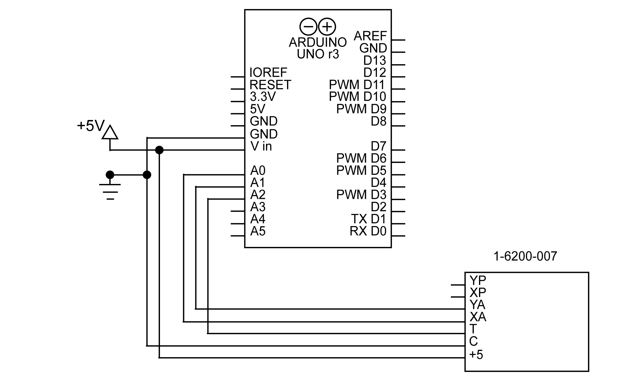
图1使用模拟量连接1-6200-007和Arduino的示意图。
请注意,1-6200-012 信号调节器没有模拟温度输出,因此必须使用 RS-232 读取温度。有关从 1-6200-012 读取温度的更多信息,请参见 RS-232 部分。
电路组装好后,可以使用Arduino的analogRead()函数读取数据。下面是一个例子。
x = analogRead(A0);
y = analogRead(A1);
温度 = analogRead(A2)。
该代码的结果将是一个原始值,代表模拟引脚上的电压。该测量的分辨率将取决于用于读取电压的硬件;在Arduino Uno上,模拟引脚的分辨率为10位。
PWM
PWM measurements are available on the 1-6200-007 signal conditioner. With PWM, the x and y tilt angles can be read from the digital XP and YP pins on the signal conditioner. There is no temperature PWM output, so that will have to be read from the analog pin. A schematic for this setup is shown in figure 2. 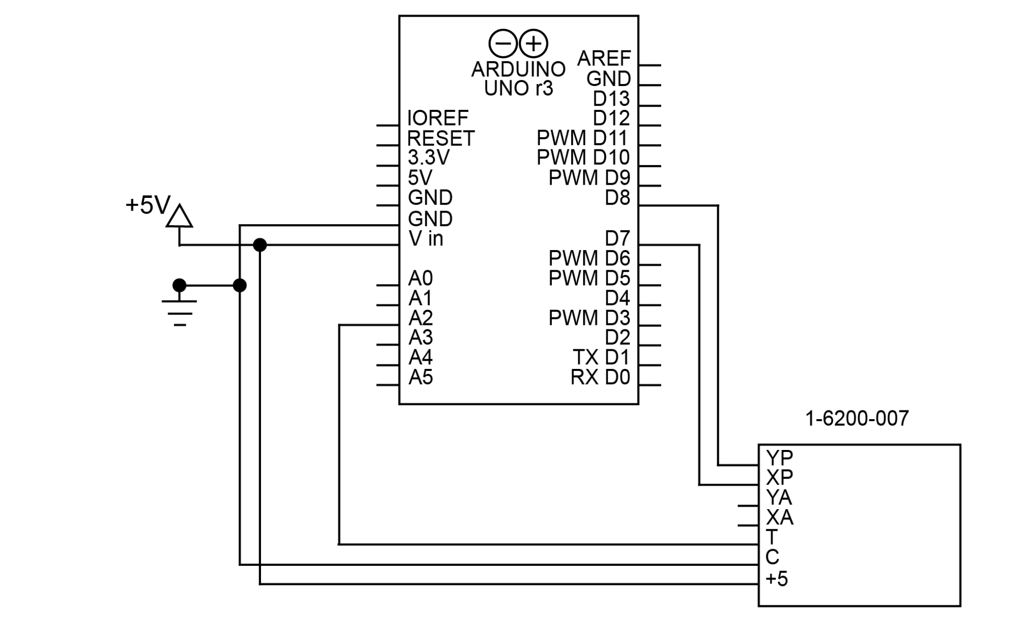
图2使用PWM将1-6200-007连接到Arduino的示意图。
注意,PWM输出可以连接到Arduino上的任何数字引脚,而不仅仅是PWM引脚。在本例中,使用了D7和D8引脚,都是非PWM引脚。
用Arduino读取PWM信号最好使用pulseIn()函数。pulseIn()函数将对脉冲在高电平或低电平状态下持续的时间进行计时。在本例中,我们将对高电平状态进行计时。
x = pulseIn(XPIN, HIGH);
y = pulseIn(YPIN, HIGH);
温度 = analogRead(A0)。

char res[50];
sprintf(res, "X: %i, Y: %i, Temperature: %i", x, y, temperature);
串行.println(res)
其结果将是以微秒为单位的脉冲长度。pulseIn()函数可以读取短至10μs的脉冲,这意味着它对高达8ms的脉冲的测量精度将类似于10位输出。如果读取它的设备能够检测到更小的脉冲,这个精度会更高。
SPI
SPI是一种同步串行通信协议,可在1-6200-005信号调节器上使用。该协议采用主/从技术,使用4个连接。MISO(主进从出)、MOSI(主出从入)、CLK(串行时钟)和SS(从动选择)。主站将通过 MOSI(1-6200-005 上的标记为 IN)向从站发送命令,而从站将通过 MISO(1-6200-005 上的标记为 OUT)作出响应。CLK 是由主站创建的时钟,用于同步从站的通信。SS 用于使能从机;该引脚是 SPI 在一条总线上支持多个设备的方式(请参阅"SPI 总线"部分以了解更多信息)。
Arduino Uno有预定义的MOSI、MISO和CL引脚。这些引脚如下表所示。
| MOSI | D11 |
| MISO | D12 |
| CLK | D13 |
这些与Arduino连接的示意图如图3所示。 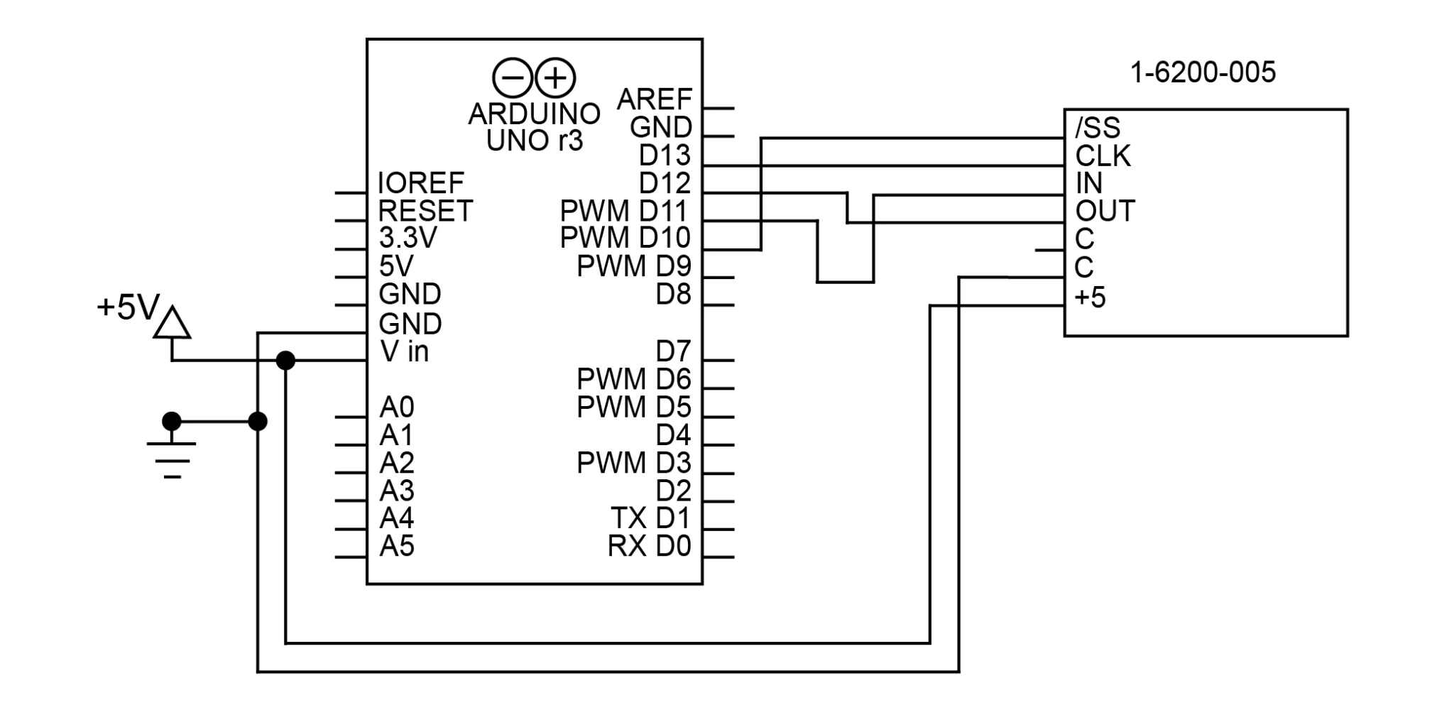
图3用SPI连接1-6200-005和Arduino的示意图。
为了与传感器通信,我们将使用Arduino的SPI库。 SPI.begin()将初始化SPI库(然而它不会打开通信)。由于该电路只有一个SPI器件,引脚10(SS)将被设置为LOW,使该引脚控制的从属器件生效。这将在整个程序中保持设置为LOW;在这个电路中没有理由禁用从机。
void setup() {
    SPI.begin(); // initialize SPI
    digitalWrite(10, LOW); // enable slave 1
}
现在我们已经初始化了库,我们必须打开与信号调节器的连接。这是通过SPI.beginTransaction()函数完成的。这个函数需要一个参数,一个SPISettings对象。这个对象将提供创建连接的所有必要信息。SPISettings对象有三个参数。
- 从机的最高时钟速度,在1-6200-005上是20Mhz。
- 第二个参数决定了SPI接口是使用最重要位优先还是最不重要位优先。对于1-6200-005来说,这是Most Significant Bit First(或MSBFIRST)。
- 第三个参数决定SPI模式;对于1-6200-005,使用SPI模式2(CPOL=1,CPHA=0)。
//开放SPI通信

SPI.beginTransaction(SPISettings(20000000, MSBFIRST, SPI_MODE2))。
SPI.transfer()函数用于发送和接收数据。它将同时发送命令,并返回从MISO引脚读取的任何数据。请注意,从机总是需要一个时钟周期来响应;因此,每个命令的结果要到下一个周期才会收到。例如,在下面的代码中,发送X轴低字节请求的函数因为这个延迟而返回X轴高字节值。
请注意,0x39命令对获得良好的测量结果至关重要。这条命令告诉电路板获得新的倾斜度测量。在下面的代码中,它在开始时发送一次,在if语句的结尾再次发送一次,在那里接收低温位。
    SPI.transfer(0x39); // update sensor data
    delay(1); // wait for SPI response
    res = SPI.transfer(0x31); // get status, request high x byte
    delay(1); // wait for SPI response

    if (res == 0x2A) { // verify sensor data updated successfully
        high = SPI.transfer(0x32); // get high x byte, request low x byte
        delay(1); // wait for SPI response
        low = SPI.transfer(0x33); // get low x byte, request high y byte
        x = (high << 8) | low; // merge low and high bytes into int

        delay(1); // wait for SPI response
        high = SPI.transfer(0x34); // get high y byte, request low y byte
        delay(1); // wait for SPI response
        low = SPI.transfer(0x35); // get low y byte, request high temperature byte
        y = (high << 8) | low; // merge low and high bytes into int

        delay(1); // wait for SPI response
        high = SPI.transfer(0x36); // get high temp byte, request low temp byte
        delay(1); // wait for SPI response
        low = SPI.transfer(0x39); // get low temperature byte, update sensor data
        temperature = (high << 8) | low; // merge low and high bytes into int
    }

    SPI.endTransaction(); // close the SPI communication
Note that the responses will be in separate high and low bytes. The code above converts these to 16-bit integers using the expression (high << 8) | low.
SPI总线
It is also possible to connect 1-6200-005 signal conditioners together in an SPI bus. An SPI Bus allows all SPI devices to share the CLK, MISO, and MOSI connections. Each slave, however, gets its own SS connection, allowing the master to select which slave it wants to communicate with. The number of SPI devices you can use at once is limited by the number of independent SS connections you can make. Figure 4 shows the schematic for 2 sensors on an SPI bus with pins D9 and D10 used as the SS signals. 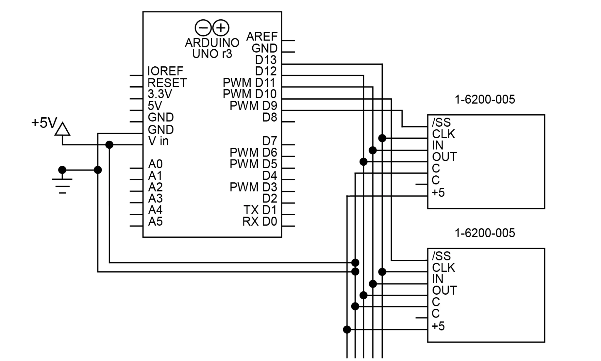
图4用SPI总线将两个1-6200-005连接到Arduino的示意图。请注意每个设备的独立/SS连接
这段代码与单片SPI器件的代码非常相似,注意SS引脚的改变是为了控制与哪个从机通信。
// open SPI communication

    SPI.beginTransaction(SPISettings(20000000, MSBFIRST, SPI_MODE2));
    digitalWrite(10, LOW); // enable the slave controlled by D10

    SPI.transfer(0x39); // request status
    delay(1);
    res = SPI.transfer(0x31); // get status, request high x byte
    delay(1);

    if (res == 0x2A) {
        hi = SPI.transfer(0x32); // get high x byte, request low x byte
        delay(1);
        lo = SPI.transfer(0x33); // get low x byte, request high y byte
        x = (hi << 8) | lo;

        delay(1);
        hi = SPI.transfer(0x34); // get high y byte, request low y byte
        delay(1);
        lo = SPI.transfer(0x35); // get low y byte, request high temperature byte
        y = (hi << 8) | lo;

        delay(1);
        hi = SPI.transfer(0x36); // get high temperature byte, request low temperature byte
        delay(1);
        lo = SPI.transfer(0x39); // get low temperature byte
        temperature = (hi << 8) | lo;
    }

    digitalWrite(10, HIGH); // disable the slave controlled by D10
    digitalWrite(9, LOW); // enable the slave controlled by D9

    SPI.transfer(0x39); // request status
    delay(1);
    res = SPI.transfer(0x31); // get status, request high x byte
    delay(1);

    if (res == 0x2A) {
        hi = SPI.transfer(0x32); // get high x byte, request low x byte
        delay(1);
        lo = SPI.transfer(0x33); // get low x byte, request high y byte
        x = (hi << 8) | lo;

        delay(1);
        hi = SPI.transfer(0x34); // get high y byte, request low y byte
        delay(1);
        lo = SPI.transfer(0x35); // get low y byte, request high temperature byte
        y = (hi << 8) | lo;

        delay(1);
        hi = SPI.transfer(0x36); // get high temperature byte, request low temperature byte
        delay(1);
        lo = SPI.transfer(0x39); // get low temperature byte
        temperature = (hi << 8) | lo;
    }

    digitalWrite(9, HIGH); // disable the slave controlled by D9
    SPI.endTransaction(); // close the SPI communication
需要注意的是,如果同时启用2个SPI从站并发送消息,信号会发生干扰,响应将无法正确读取。
RS-232
RS-232(TIA-232)是一种通用的串行通信协议。1-6200-006和1-6200-012信号调节器上都有 3 线制的 RS-232 版本。连接RS-232包括将地线连接在一起,并将每个Rx连接到其他设备的Tx。
在这个应用程序中,我们将使用Arduino的SoftwareSerial库来创建一个虚拟的串口来使用。这个库使我们能够反转端口上的信号,这是与传感器通信所必需的。它还能保持硬件串口可用于其他用途。要创建RS-232的电路,只需将D10(我们的虚拟RX引脚)连接到OUT,D11(我们的虚拟TX)连接到IN。这如图5所示。 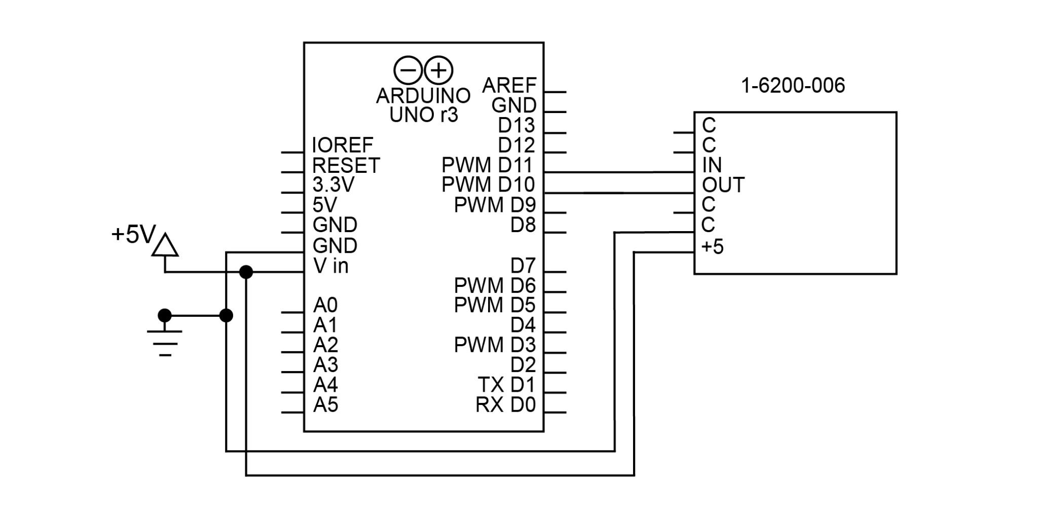
图5 用RS-232和SoftwareSerial库将1-6200-006连接到Arduino的示意图。
使用SoftwareSerial,可以用以下代码初始化虚拟串口。
SoftwareSerial Sensor(10, 11, true); //RX, TX, inverse
void setup() {
    Sensor.begin(9600); //RX, TX, invert
}
请注意,具有UART TTL串口的设备(如Arduino)需要一个倒置的串口连接,否则将无法通信。对于Arduino来说,在创建虚拟串口时,可以通过第三个参数来实现("true"表示倒置信号)。
通过RS-232读取倾斜度,首先要发送想要数据的命令,然后从端口读取数据。读取X轴、Y轴和温度值的代码如下。
Sensor.print('x'); // send command for x axis tilt
delay(50); // delay to give time for response
b = 0;
while (Sensor.available() != 0 && b < 8) {
    x[b++] = Sensor.read(); // read received bytes into char array
}

Sensor.print('y'); // send command for y axis tilt
delay(50);
b = 0;
while (Sensor.available() != 0 && b < 8) {
    y[b++] = Sensor.read();
}

Sensor.print('t'); // send command for temperature
delay(50);
b = 0;
while (Sensor.available() != 0 && b < 8) {
    temperature[b++] = Sensor.read();
}
所有RS-232命令的定义都可以在信号调节器的数据表中找到。
该代码的响应将是一个8字节的字符数组,以换行和回车字符(0x0a, 0x0d)结束。这将不是一个字符串,所以很可能必须将其转换为字符串。如果有必要,也可以将其转换为一个int。
// 将char数组转换为字符串
    x[b - 2] = '0'。

   // 将字符串转换为16位int
    xInt = atoi(x);
上面的代码将换行符替换为空字符,在最后一个字符之后立即终止字符串。这需要使用b变量,所以很可能要在收到测量结果后立即进行。为了在不使用b变量的情况下实现这一点,终止字符也可以放在数组的末尾,但这会留下尾部的空格和字符。
RS-485
RS-485(TIA-485)是一种串行通信标准,在长距离和电气噪声环境中工作良好。它在1-6200-008信号调节器上可以使用。Arduino Uno本身并不支持RS-485,但可以使用一个转换器来方便与我们的任何RS-485产品进行通信。
在大多数RS-485转换器上,DI(数据输入)和RO(接收输出)分别是Rx和Tx。RE(接收使能)和DE(数据使能)控制转换器何时发送和接收RS-485数据;这些通常可以连接在一起并进行切换(高电平发送数据,低电平接收数据)。转换器上的A、B连接与信号调节器上的A、B连接。该电路的原理图如图6所示。 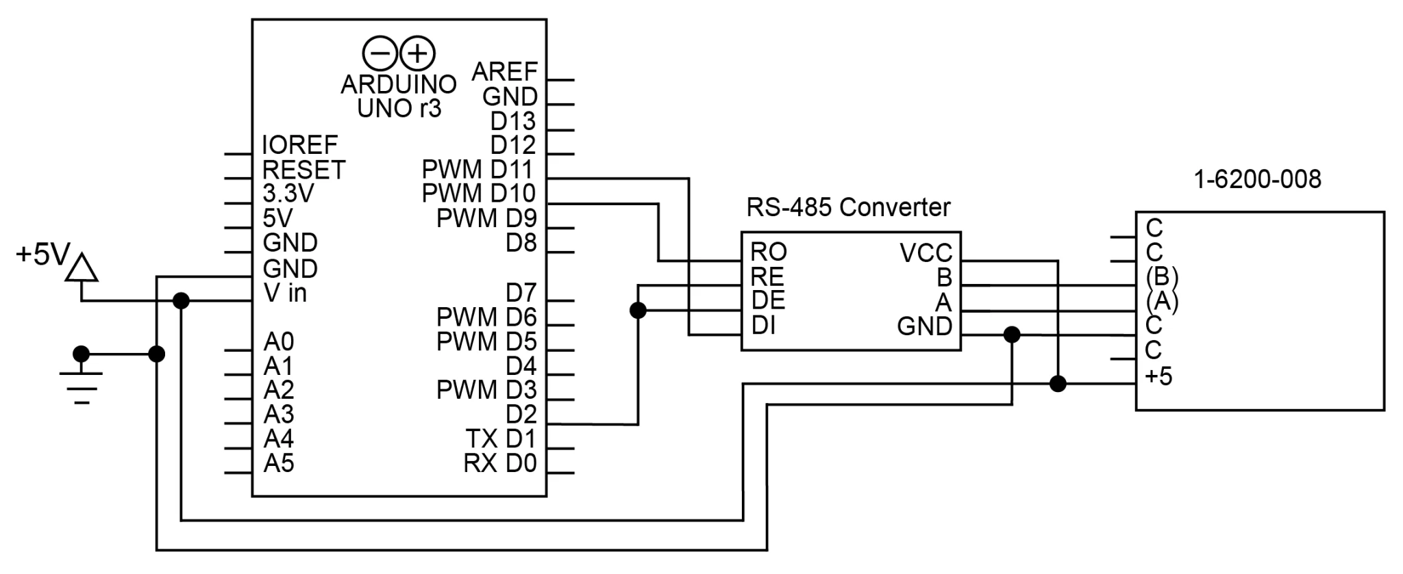
图6用RS-485连接1-6200-008和Arduino的示意图。RS-485转换器作为中介
用于与信号调节器通信的 RS-485 命令使用以下格式。
*xxyy#
xx 是发送命令的地址。默认情况下,1-6200-008 上的地址为 99。默认情况下,1-6200-008 上的地址为 99。yy 是命令本身。# 表示命令的结束。例如,在地址 99 上读取 X 轴倾斜度的命令是 *9911#。所有可用的命令都可以在 1-6200-008 数据表上找到。
在RS-232转RS-485转换器在线的情况下,这些命令可以用RS-232发送给转换器。然后,转换器将把这些命令用RS-485发送给信号调节器。设置功能将与RS-232信号调节器相同。下面的代码显示了如何使用这种配置来读取信号调节器的数据。
// x axis tilt
    digitalWrite(9, HIGH); // enable transmission
    Sensor.print("*9911#"); // send x axis command
    digitalWrite(9, LOW); // enable reception
    delay(25); // wait for sensor to respond
    b = 0;
    while (Sensor.available()) {
        x[b++] = Sensor.read(); // store response in a char array
    }

    // y axis tilt
    digitalWrite(9, HIGH); // enable transmission
    Sensor.print("*9921#"); // send y axis command
    digitalWrite(9, LOW); // enable reception
    delay(25);
    b = 0;
    while (Sensor.available()) {
        y[b++] = Sensor.read(); // store response in char array
    }

    // temperature
    digitalWrite(9, HIGH); // enable transmission
    Sensor.print("*9941#"); // send temperature command
    digitalWrite(9, LOW); // enable reception
    delay(25);
    b = 0;
    while (Sensor.available()) {
        temperature[b++] = Sensor.read(); // store response
    }
和RS-232一样,响应将是一个字符数组,由一个新行和回车结束。如果你想把数组当作一个字符串来处理,你必须附加空字符('/0')。
寻址RS-485
可以将最多 32 个1-6200-008信号调节器连接到一条总线上。然后可以为信号调节器分配地址,为每个传感器提供一种确定是否响应的方式。请注意,重要的是要避免连接多个具有相同地址的传感器,因为传感器会干扰彼此的传输。
默认情况下,信号调节器的地址为 99。要更改它,请确保它是唯一连接到该地址的设备。然后,使用命令*xx81Azz#,其中xx是当前地址,zz是新地址。比如说,*xx81Azz#。
Sensor.print("*9981A01#");//将地址从99改为01。
一旦地址被更改,您将无法再使用以99开头的命令访问传感器。取而代之的是,新地址01将取代所有命令中的99。例如,运行上述命令后,读取产品信息的命令将从*9980#变为*0180#。
一旦每个传感器被分配了一个唯一的地址,它们就可以被连接到电路中。每个信号调节器都可以连接到同一总线上,无需额外的组件或连接。见图7所示的原理图。 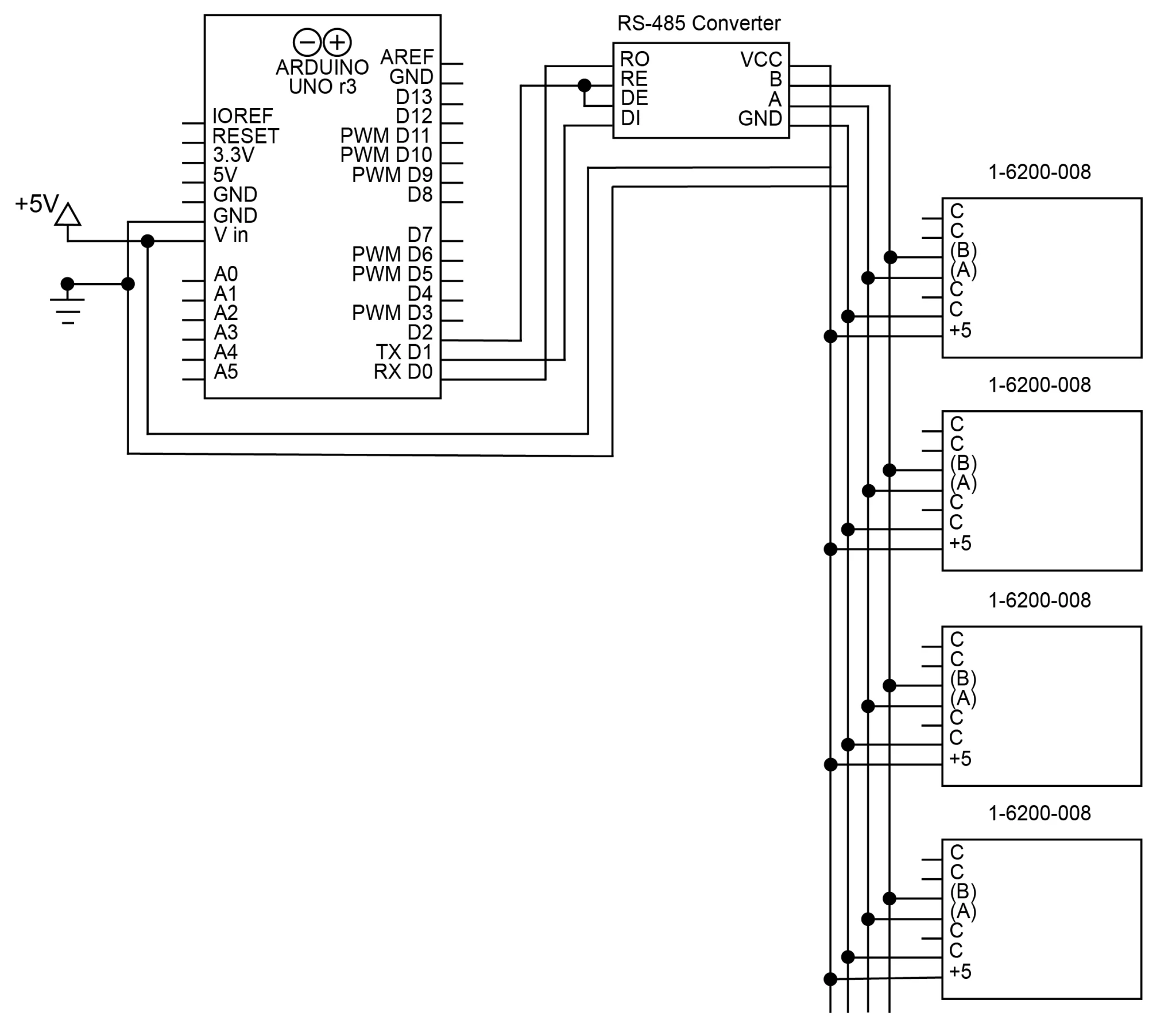
图7将(4个)1-6200-008信号调节器连接到带RS-485的Arduino的示意图。
下面给出了一个从多个寻址RS-485传感器读取数据的程序示例。这段代码是为连接到4个传感器的电路编写的,地址为8-11。
char addr[4][3] = {"08", "09", "10", "11"};
for (int i = 0; i < 4; i++) { // run this code for every address
    // x axis tilt
    digitalWrite(9, HIGH); // enable transmission
    sprintf(cmd, "*%2s11#", addr[i]); // create x axis command
    Sensor.print(cmd); // send x axis command
    digitalWrite(9, LOW); // enable reception
    delay(25); // wait for sensor to respond
    b = 0;
    while (Sensor.available()) {
        x[b++] = Sensor.read(); // store response from sensor in a char array
    }

    // y axis tilt
    digitalWrite(9, HIGH); // enable transmission
    sprintf(cmd, "*%2s21#", addr[i]); // create command
    Sensor.print(cmd); // send command
    digitalWrite(9, LOW); // enable reception
    delay(25);
    b = 0;
    while (Sensor.available()) {
        y[b++] = Sensor.read(); // store response
    }

    // temperature
    digitalWrite(9, HIGH); // enable transmission
    sprintf(cmd, "*%2s41#", addr[i]); // create command
    Sensor.print(cmd); // send command
    digitalWrite(9, LOW); // enable reception
    delay(25);
    b = 0;
    while (Sensor.available()) {
        temperature[b++] = Sensor.read(); // store response
    }
}
响应将是包含16位数字的ASCII字符的8字节字符数组。