


説明
このアプリケーションノートでは、電解チルトセンサとシグナルコンディショナからチルト測定を行う方法について説明します。フレデリックス社のシグナルコンディショナで利用可能な各プロトコルの回路図とコードをカバーしています。すべての例は、Arduino Unoのコードと回路を示すので、他のプラットフォームを使用する場合は、コードに違いがあります。各例では、センサーからの生出力をさまざまな単位で提供します。これらの単位は、アプリケーションノート1005で説明されている方法を使用して、度数に変換することができます。
アナログ
Both the 1-6200-007 そして 1-6200-012 signal conditioners have analog outputs. On the 1-6200-007, both axes and the temperature are output from pins XA, YA, and T respectively. Connecting to the Arduino requires direct connections from the signal conditioner to the analog input pins of the Arduino. 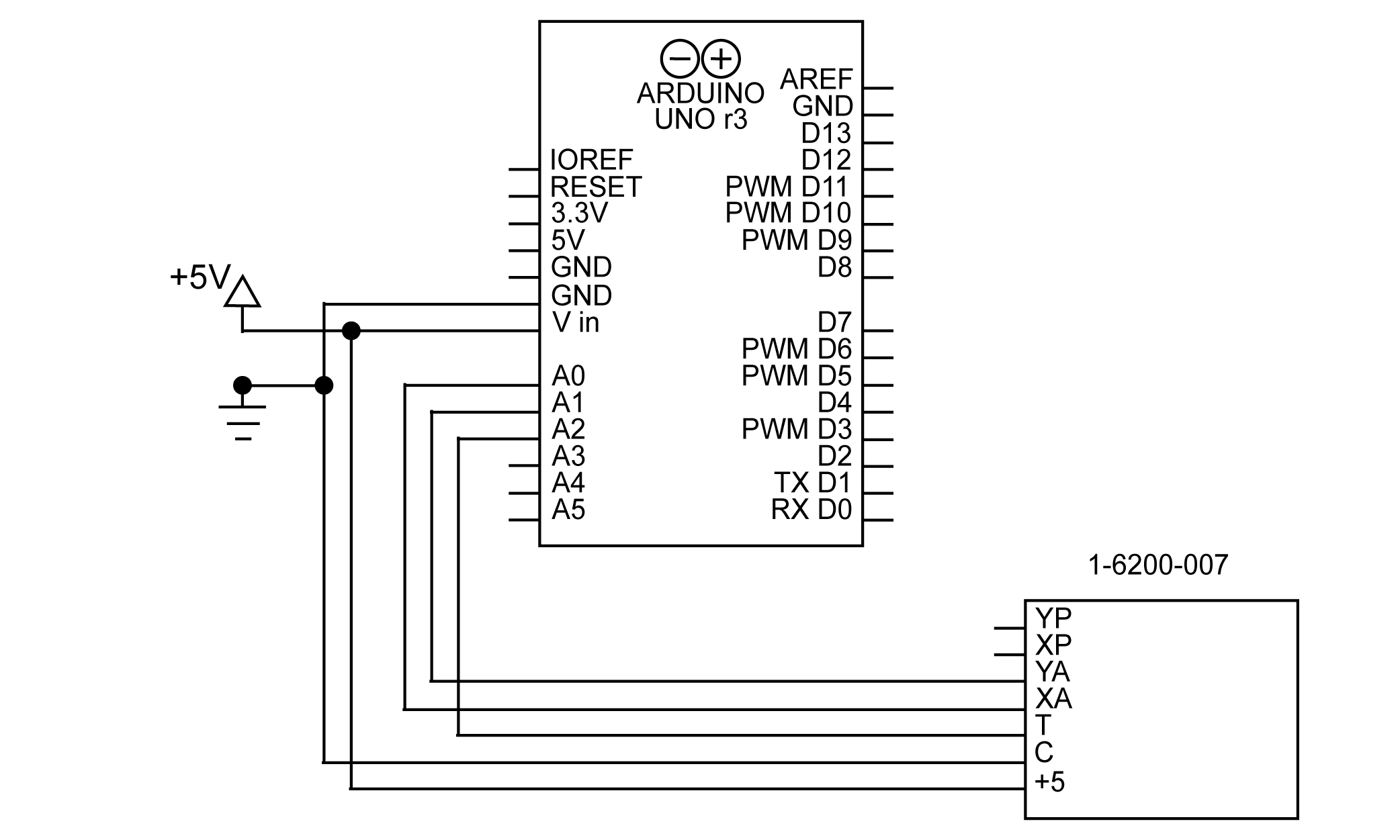
図 1 1-6200-007 と Arduino をアナログで接続するための回路図
なお、シグナルコンディショナ 1-6200-012 にはアナログ温度出力がありませんので、RS-232 で温度を読み取る必要があります。1-6200-012 からの温度の読み取りについては、「RS-232」の項を参照してください。
回路を組み立てた状態で、ArduinoのanalogRead()関数を使ってデータを読み込むことができます。その例を以下に示します。
x = analogRead(A0).
y = analogRead(A1).
温度 = analogRead(A2).
このコードの結果は、アナログ・ピンの電圧を表す生の値になります。この測定の分解能は、電圧の読み取りに使用されるハードウェアに依存します。
PWM
PWM measurements are available on the 1-6200-007 signal conditioner. With PWM, the x and y tilt angles can be read from the digital XP and YP pins on the signal conditioner. There is no temperature PWM output, so that will have to be read from the analog pin. A schematic for this setup is shown in figure 2. 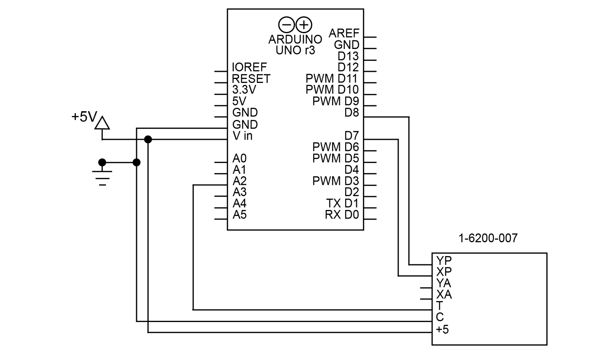
図 21-6200-007 と Arduino を PWM で接続するための回路図
PWM出力は、PWMピンだけでなく、Arduino上の任意のデジタルピンに接続することができることに注意してください。この例では、D7とD8のピンを使用していますが、どちらもPWMピンではありません。
ArduinoでPWM信号を読み出すには、pulseIn()関数を使用するのが最適です。pulseIn()関数は、パルスがハイまたはローの状態でどれくらいの時間続くかを計測します。ここでは、ハイ・ステートの時間を設定します。
x = pulseIn(XPIN, HIGH).
y = pulseIn(YPIN, HIGH).
温度 = analogRead(A0).

char res[50].
sprintf(res, "X: %i, Y: %i, Temperature: %i", x, y, temperature).
Serial.println(res)
結果は、マイクロ秒単位のパルスの長さになります。pulseIn() 関数は 10μs という短いパルスを読み取ることができますが、これは 8ms までのパルスの測定が 10 ビット出力と同等の精度を持つことを意味します。この精度は、それを読み取るデバイスがより小さなパルスを検出できる場合に高くなります。
エスピーアイ
SPI は、1-6200-005シグナルコンディショナで利用可能な同期シリアル通信プロトコルです。このプロトコルは、4 つの接続を使用してマスター/スレーブ技術で動作します。MISO(Master In Slave Out)、MOSI(Master Out Slave In)、CLK(Serial Clock)、SS(Slave Select)の4つの接続を使用します。マスターはMOSI(1-6200-005のINと表示されている)を介してスレーブにコマンドを送信し、スレーブはMISO(1-6200-005のOUTと表示されている)を介して応答します。CLK はスレーブの通信を同期させるためにマスターが作成するクロックです。SS はスレーブをイネーブルにするために使用されます。このピンは SPI が 1 つのバス上で複数のデバイスをサポートする方法を示しています(詳細は「SPI バス」のセクションを参照)。
Arduino Unoには、MOSI、MISO、CL用の定義済みピンがあります。これらを以下の表に示します。
| きんぞくさん | D11 |
| ミソ | D12 |
| CLK | D13 |
これらをArduinoに接続するための回路図を図3に示します。 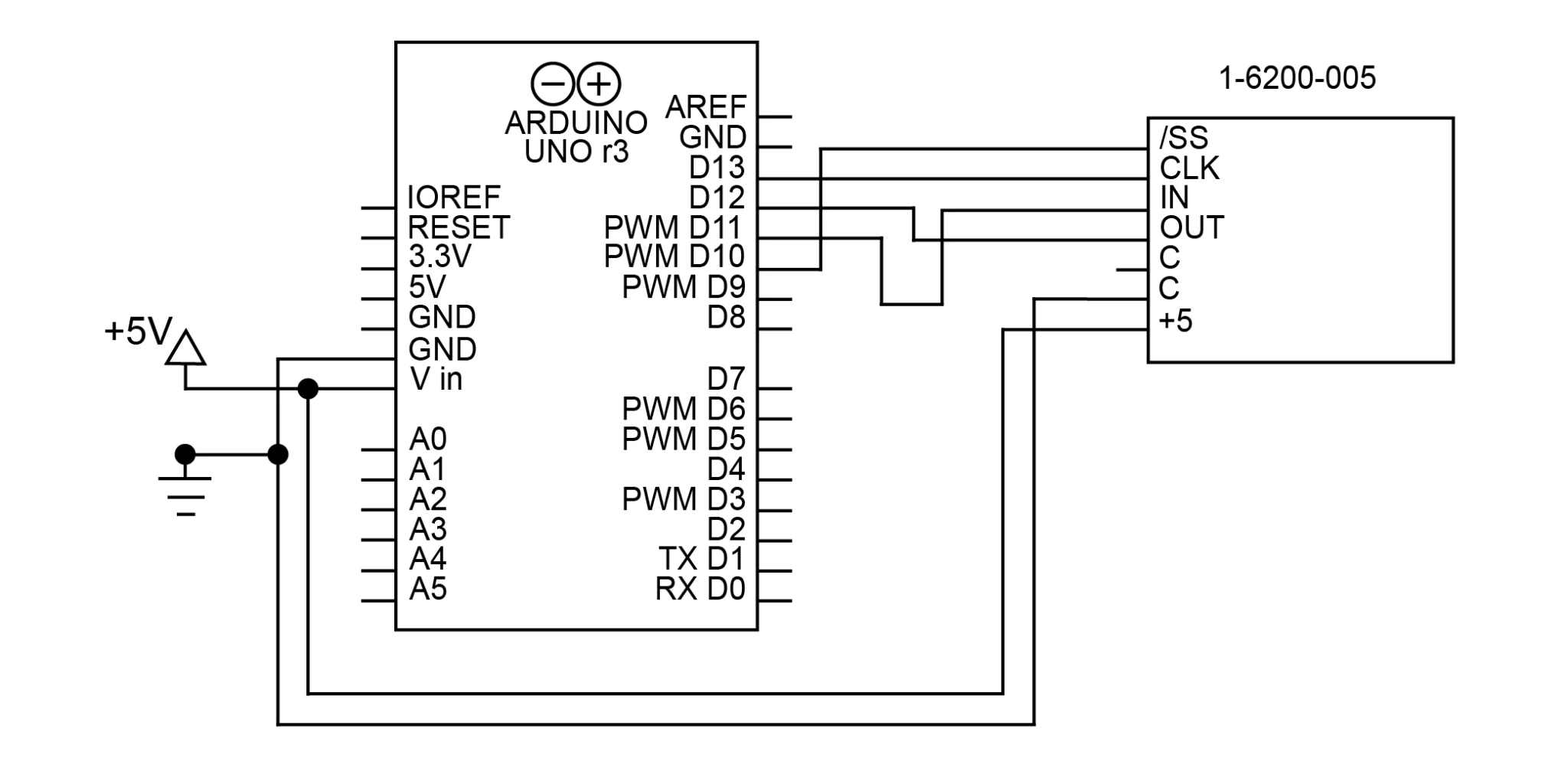
図 31-6200-005 と Arduino を SPI で接続するための回路図
センサーとの通信には、ArduinoのSPIライブラリを使用します。 SPI.begin()でSPIライブラリを初期化します(ただし、通信は開きません)。この回路はSPIデバイスが1つしかないので、10番ピン(SS)をLOWにして、そのピンで制御されるスレーブを有効にします。この状態はプログラム中ずっとLOWのままなので、この回路でスレーブを無効にする必要はありません。
void setup() {
    SPI.begin(); // initialize SPI
    digitalWrite(10, LOW); // enable slave 1
}
ライブラリを初期化したので、シグナルコンディショナーとの接続をオープンにする必要があります。これは、SPI.beginTransaction()関数を使用して行います。この関数は1つの引数、SPISettingsオブジェクトを取ります。このオブジェクトは、接続を作成するために必要なすべての情報を提供します。SPISettings オブジェクトには 3 つの引数があります。
- スレーブの最大クロック速度は、1-6200-005では20Mhzです。
- 2 番目の引数は、SPI インターフェイスが最上位ビットを使用するか最下位ビットを使用するかを決定します。1-6200-005 の場合、これは Most Significant Bit First ( またはMSBFIRST) です。
- 1-6200-005では、SPIモード2(CPOL=1, CPHA=0)が使用されます。
// オープンなSPI通信
SPI.beginTransaction(SPISettings(20000000, MSBFIRST, SPI_MODE2))。
SPI.transfer()関数はデータの送受信に使用されます。これは同時にコマンドを送信し、MISOピンから読み込んだものを返します。スレーブが応答するまでには常に1 クロックサイクルかかりますので、各コマンドの結果は次のサイクルまで受信できません。例えば、以下のコードでは、X 軸のローバイト要求を送信する関数は、この遅延のために X 軸のハイバイト値を返します。
0x39 コマンドは、良好な測定値を得るために不可欠であることに注意してください。このコマンドは、ボードに傾きの新しい測定値を取得するように指示します。以下のコードでは、最初に一度だけ送信され、if文の最後にもう一度送信され、低温ビットを受信しています。
    SPI.transfer(0x39); // update sensor data
    delay(1); // wait for SPI response
    res = SPI.transfer(0x31); // get status, request high x byte
    delay(1); // wait for SPI response

    if (res == 0x2A) { // verify sensor data updated successfully
        high = SPI.transfer(0x32); // get high x byte, request low x byte
        delay(1); // wait for SPI response
        low = SPI.transfer(0x33); // get low x byte, request high y byte
        x = (high << 8) | low; // merge low and high bytes into int

        delay(1); // wait for SPI response
        high = SPI.transfer(0x34); // get high y byte, request low y byte
        delay(1); // wait for SPI response
        low = SPI.transfer(0x35); // get low y byte, request high temperature byte
        y = (high << 8) | low; // merge low and high bytes into int

        delay(1); // wait for SPI response
        high = SPI.transfer(0x36); // get high temp byte, request low temp byte
        delay(1); // wait for SPI response
        low = SPI.transfer(0x39); // get low temperature byte, update sensor data
        temperature = (high << 8) | low; // merge low and high bytes into int
    }

    SPI.endTransaction(); // close the SPI communication
Note that the responses will be in separate high and low bytes. The code above converts these to 16-bit integers using the expression (high << 8) | low.
SPIバス
It is also possible to connect 1-6200-005 signal conditioners together in an SPI bus. An SPI Bus allows all SPI devices to share the CLK, MISO, and MOSI connections. Each slave, however, gets its own SS connection, allowing the master to select which slave it wants to communicate with. The number of SPI devices you can use at once is limited by the number of independent SS connections you can make. Figure 4 shows the schematic for 2 sensors on an SPI bus with pins D9 and D10 used as the SS signals. 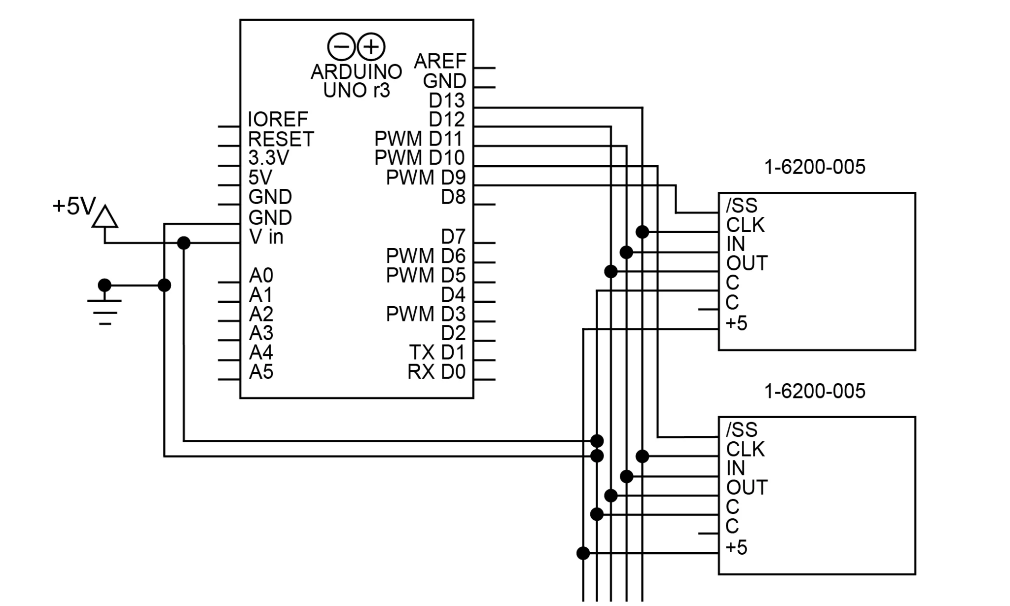
図 41-6200-005 を 2 つの 1-6200-005 と Arduino を SPI バスで接続するための回路図。各デバイスの /SS 接続が別々になっていることに注意してください。
このコードは単一のSPIデバイスのコードと非常に似ていますが、どのスレーブと通信するかを制御するためにSSピンが変更されていることに注意してください。
// open SPI communication

    SPI.beginTransaction(SPISettings(20000000, MSBFIRST, SPI_MODE2));
    digitalWrite(10, LOW); // enable the slave controlled by D10

    SPI.transfer(0x39); // request status
    delay(1);
    res = SPI.transfer(0x31); // get status, request high x byte
    delay(1);

    if (res == 0x2A) {
        hi = SPI.transfer(0x32); // get high x byte, request low x byte
        delay(1);
        lo = SPI.transfer(0x33); // get low x byte, request high y byte
        x = (hi << 8) | lo;

        delay(1);
        hi = SPI.transfer(0x34); // get high y byte, request low y byte
        delay(1);
        lo = SPI.transfer(0x35); // get low y byte, request high temperature byte
        y = (hi << 8) | lo;

        delay(1);
        hi = SPI.transfer(0x36); // get high temperature byte, request low temperature byte
        delay(1);
        lo = SPI.transfer(0x39); // get low temperature byte
        temperature = (hi << 8) | lo;
    }

    digitalWrite(10, HIGH); // disable the slave controlled by D10
    digitalWrite(9, LOW); // enable the slave controlled by D9

    SPI.transfer(0x39); // request status
    delay(1);
    res = SPI.transfer(0x31); // get status, request high x byte
    delay(1);

    if (res == 0x2A) {
        hi = SPI.transfer(0x32); // get high x byte, request low x byte
        delay(1);
        lo = SPI.transfer(0x33); // get low x byte, request high y byte
        x = (hi << 8) | lo;

        delay(1);
        hi = SPI.transfer(0x34); // get high y byte, request low y byte
        delay(1);
        lo = SPI.transfer(0x35); // get low y byte, request high temperature byte
        y = (hi << 8) | lo;

        delay(1);
        hi = SPI.transfer(0x36); // get high temperature byte, request low temperature byte
        delay(1);
        lo = SPI.transfer(0x39); // get low temperature byte
        temperature = (hi << 8) | lo;
    }

    digitalWrite(9, HIGH); // disable the slave controlled by D9
    SPI.endTransaction(); // close the SPI communication
2 つの SPI スレーブを同時に有効にしてメッセージを送信すると、信号が干渉してレスポンスが正しく読み込まれないことに注意してください。
RS-232
RS-232(TIA-232)は、一般的なシリアル通信プロトコルです。1-6200-006と1-6200-012 には、3 線式の RS-232 があります。RS-232 の接続は、グランドを一緒に接続し、各 Rx を他の装置の Tx に接続することで構成されています。
このアプリケーションでは、ArduinoのSoftwareSerialライブラリを使用して、使用する仮想シリアルポートを作成します。このライブラリを使うことで、センサーとの通信に必要なポートの信号を反転させることができます。また、ハードウェアのシリアルポートを他の用途に利用できるようにしておきます。RS-232 用の回路を作成するには、D10(仮想 RX ピン)を OUT に、D11(仮想 TX)を IN に接続します。これは図 5 に示されています。 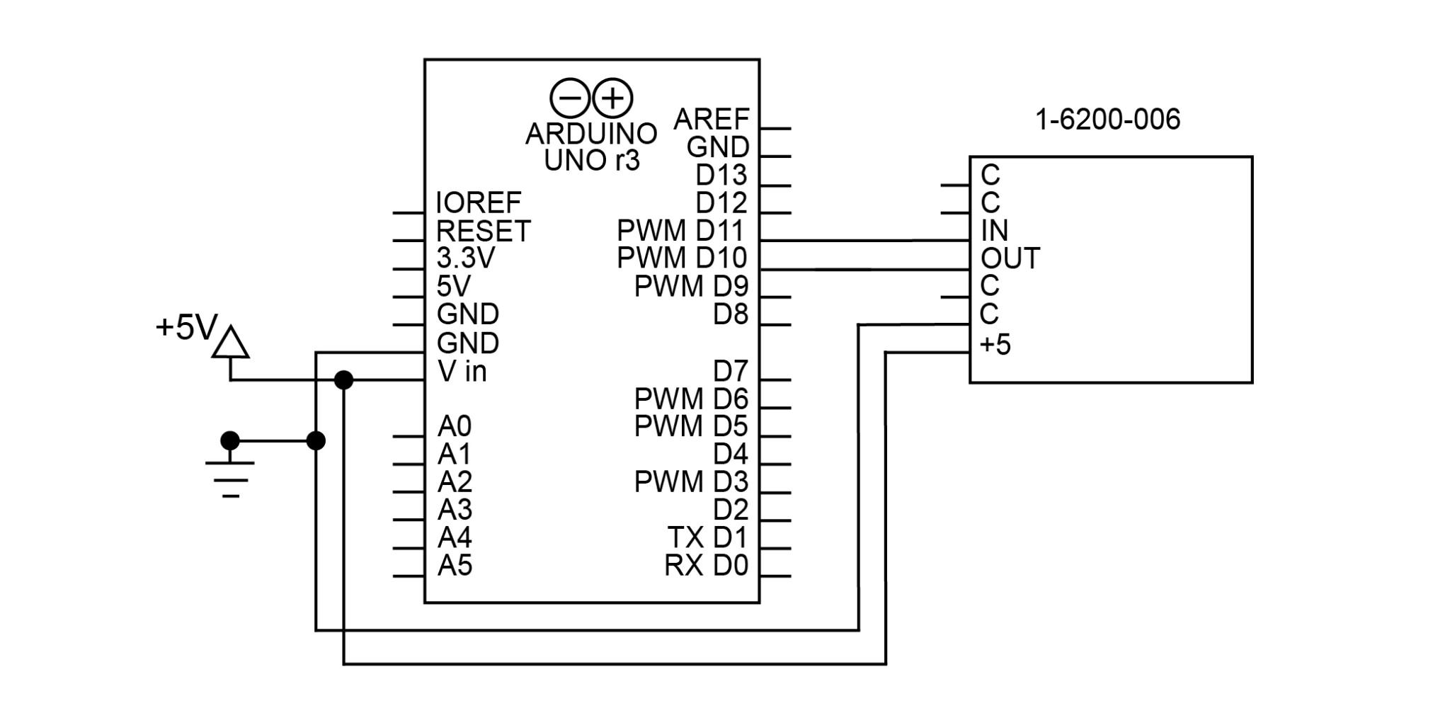
図 5 1-6200-006 と Arduino を RS-232 と SoftwareSerial ライブラリで接続するための回路図
SoftwareSerialを使用して、以下のコードで仮想シリアルポートを初期化することができます。
SoftwareSerial Sensor(10, 11, true); //RX, TX, inverse
void setup() {
    Sensor.begin(9600); //RX, TX, invert
}
UART TTLシリアルポート(Arduinoのような)を持つデバイスは、反転シリアル接続が必要で、そうしないと通信できないことに注意してください。Arduinoでは、仮想シリアルポートを作成する際に、第3引数でこれを行います(反転信号の場合は"true")。
RS-232 経由で傾きを読み取るには、まず、欲しいデータのコマンドを送信し、ポートからデータを読み込みます。X軸、Y軸、温度値を読み取るコードは以下の通りです。
Sensor.print('x'); // send command for x axis tilt
delay(50); // delay to give time for response
b = 0;
while (Sensor.available() != 0 && b < 8) {
    x[b++] = Sensor.read(); // read received bytes into char array
}

Sensor.print('y'); // send command for y axis tilt
delay(50);
b = 0;
while (Sensor.available() != 0 && b < 8) {
    y[b++] = Sensor.read();
}

Sensor.print('t'); // send command for temperature
delay(50);
b = 0;
while (Sensor.available() != 0 && b < 8) {
    temperature[b++] = Sensor.read();
}
すべてのRS-232コマンドの定義は,シグナルコンディショナのデータシートに記載されています。
このコードからのレスポンスは、改行文字とキャリッジリターン文字 (0x0a, 0x0d) で終わる 8 バイトの文字配列になります。これは文字列ではないので、ほとんどの場合文字列に変換する必要があります。必要であれば、int に変換することもできます。
// char配列を文字列に変換
    x[b - 2] = '\0'.

   // 文字列を16ビットのintに変換します.
    xInt = atoi(x)。
上のコードは、改行文字をヌル文字に置き換え、最後の文字の直後に文字列を終了させています。これはb変数を使用する必要があるので、測定を受信した直後に行う必要があるでしょう。b変数を使用せずにこれを実現するには、終了文字を配列の最後に配置することもできますが、これは末尾にスペースと文字を残すことになります。
RS-485
RS-485(TIA-485)は、長距離や電気的にノイズの多い環境でも動作するシリアル通信規格です。1-6200-008シグナルコンディショナーで利用できます。Arduino Unoは単体ではRS-485をサポートしていませんが、コンバータを使用することで、当社のRS-485製品との通信を容易にすることができます。
ほとんどの RS-485 コンバータでは、DI (Data In) と RO (Receive Out) がそれぞれ Rx と Tx となります。RE(受信イネーブル)とDE(データイネーブル)は、コンバータがRS-485データを送受信するタイミングを制御します。コンバータのAとBの接続は、シグナルコンディショナのAとBに接続されています。この回路の回路図を図6に示します。 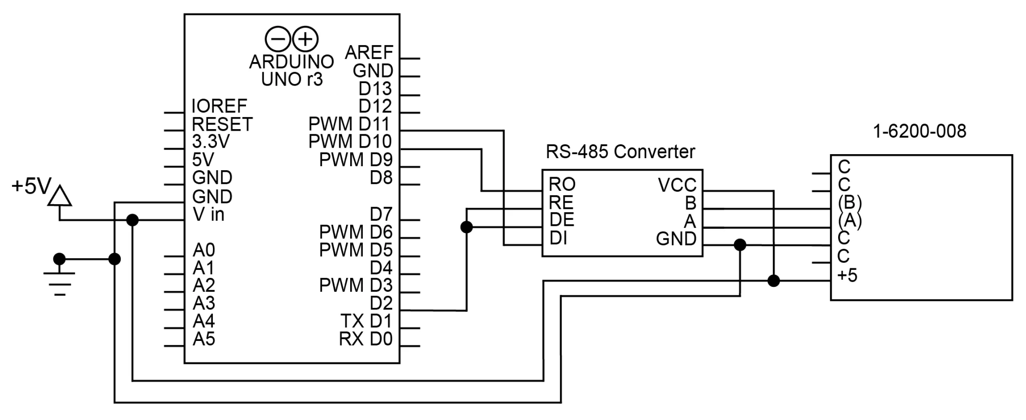
図 61-6200-008 と Arduino を RS-485 で接続するための回路図。RS-485コンバータを仲介に使用
シグナルコンディショナとの通信に使用する RS-485 コマンドは以下の形式を使用します。
*xxyyy#
xx はコマンドの送信先アドレスです。デフォルトでは、1-6200-008では99になります。はコマンドの終了を示します。例えば、アドレス 99 の x 軸の傾きを読み取るコマンドは *9911# です。使用可能なコマンドはすべて、1-6200-008 データシートに記載されています。
RS-232 から RS-485 コンバータをインラインで使用すると、これらのコマンドは RS-232 を使用してコンバータに送信することができます。コンバータはRS-485のシグナルコンディショナにこれらのコマンドを送信します。セットアップ機能は RS-232 シグナルコンディショナと同じです。以下のコードは、この設定を使ってシグナルコンディショナからデータを読み出す方法を示しています。
// x axis tilt
    digitalWrite(9, HIGH); // enable transmission
    Sensor.print("*9911#"); // send x axis command
    digitalWrite(9, LOW); // enable reception
    delay(25); // wait for sensor to respond
    b = 0;
    while (Sensor.available()) {
        x[b++] = Sensor.read(); // store response in a char array
    }

    // y axis tilt
    digitalWrite(9, HIGH); // enable transmission
    Sensor.print("*9921#"); // send y axis command
    digitalWrite(9, LOW); // enable reception
    delay(25);
    b = 0;
    while (Sensor.available()) {
        y[b++] = Sensor.read(); // store response in char array
    }

    // temperature
    digitalWrite(9, HIGH); // enable transmission
    Sensor.print("*9941#"); // send temperature command
    digitalWrite(9, LOW); // enable reception
    delay(25);
    b = 0;
    while (Sensor.available()) {
        temperature[b++] = Sensor.read(); // store response
    }
RS-232 のように、応答は、改行とキャリッジリターンで終わる文字配列になります。もし配列を文字列として扱いたい場合は、ヌル文字('\0')を追加しなければなりません。
アドレス付きRS-485
1つのバスに最大 32 個の1-6200-008シグナルコンディショナを接続することができます。シグナルコンディショナにはアドレスを割り当てることができ、各センサが応答するかどうかを判断する方法を提供します。複数のセンサーを同じアドレスで接続すると、センサー同士の通信が干渉してしまいますので注意してください。
デフォルトでは、シグナルコンディショナーのアドレスは 99 になっています。変更するには、そのアドレスを持つ唯一の接続デバイスであることを確認してください。xx は現在のアドレス、zz は新しいアドレスです。例えば、以下のようになります。
Sensor.print("*9981A01#"); // アドレスを 99 から 01 に変更します。
アドレスを変更すると、99で始まるコマンドを使用してセンサーにアクセスすることができなくなります。その代わりに、新しいアドレス01がすべてのコマンドで99 の代わりに使用されます。例えば、製品情報を読み取るコマンドは、上記のコマンドを実行すると*9980#から*0180#に変更されます。
各センサに固有のアドレスが割り当てられると、それらを回路に取り付けることができます。各シグナルコンディショナは、追加のコンポーネントや接続を必要とせず、同じバスに接続することができます。これを示す回路図を図7に示します。 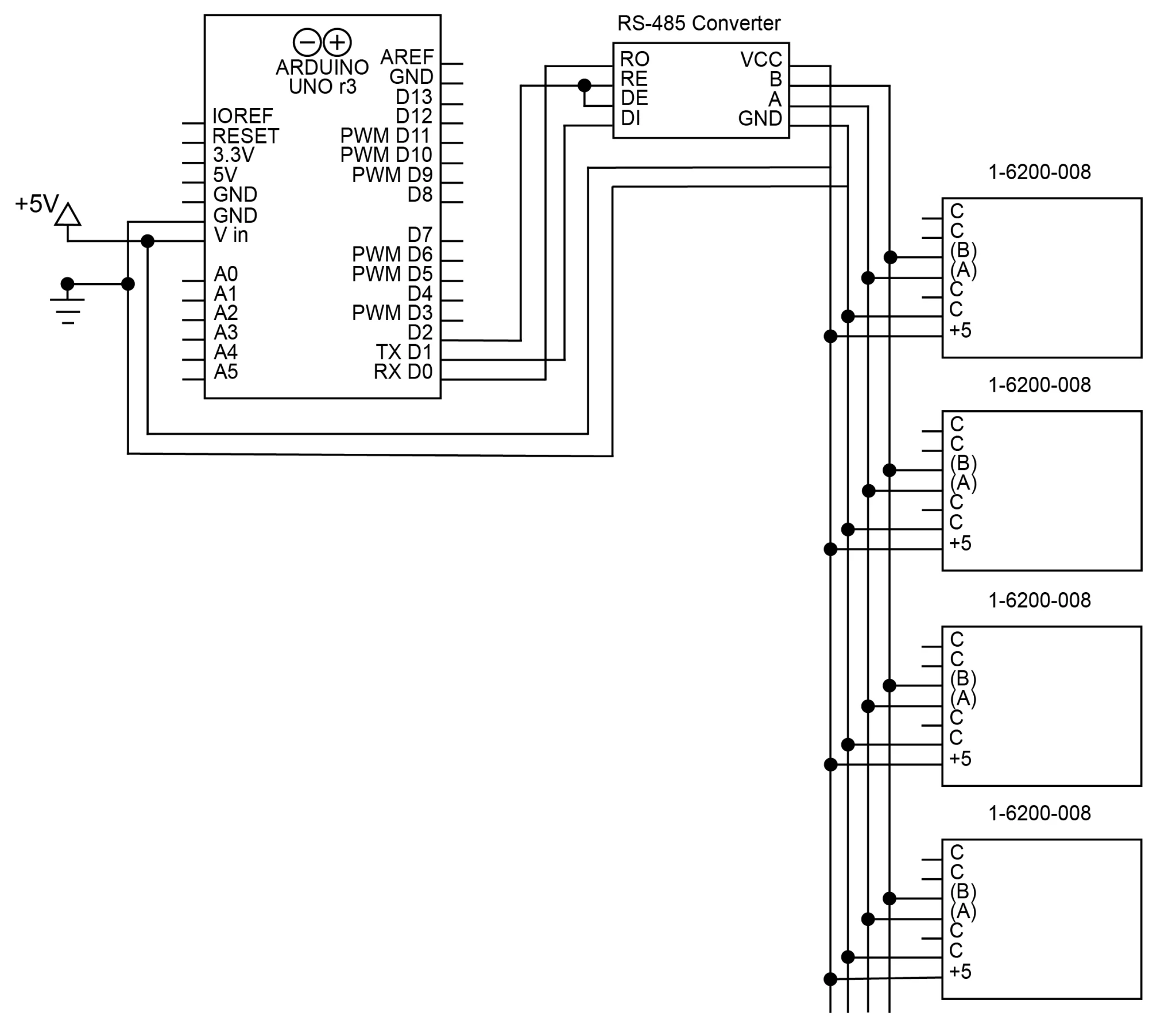
図 71-6200-008 シグナルコンディショナ(4 台)を RS-485 で Arduino に接続するための回路図
複数のアドレスのRS-485センサから読み出すプログラムの例を以下に示します。このコードは、4 つのセンサ(アドレス 8~11)に接続された回路用に書かれています。
char addr[4][3] = {"08", "09", "10", "11"};
for (int i = 0; i < 4; i++) { // run this code for every address
    // x axis tilt
    digitalWrite(9, HIGH); // enable transmission
    sprintf(cmd, "*%2s11#", addr[i]); // create x axis command
    Sensor.print(cmd); // send x axis command
    digitalWrite(9, LOW); // enable reception
    delay(25); // wait for sensor to respond
    b = 0;
    while (Sensor.available()) {
        x[b++] = Sensor.read(); // store response from sensor in a char array
    }

    // y axis tilt
    digitalWrite(9, HIGH); // enable transmission
    sprintf(cmd, "*%2s21#", addr[i]); // create command
    Sensor.print(cmd); // send command
    digitalWrite(9, LOW); // enable reception
    delay(25);
    b = 0;
    while (Sensor.available()) {
        y[b++] = Sensor.read(); // store response
    }

    // temperature
    digitalWrite(9, HIGH); // enable transmission
    sprintf(cmd, "*%2s41#", addr[i]); // create command
    Sensor.print(cmd); // send command
    digitalWrite(9, LOW); // enable reception
    delay(25);
    b = 0;
    while (Sensor.available()) {
        temperature[b++] = Sensor.read(); // store response
    }
}
応答は、16ビットの数値に対するASCII文字を含む8バイトの文字配列となります。