1. Product Information
1.1 Description
The 0729-1757-99 and 0729-1758-99 Single Axis Programmable Tilt Switches utilizes a 0717-4319-99 Fredericks wide range electrolytic tilt sensor and signal conditioner. Its robust plastic housing provides excellent durability and environmental protection. This tilt switch has superior tolerances and unit to unit performance. Its low-profile housing and economic design make it an ideal solution for a versatile range of applications in various markets and industries.
The tilt switch is field programmable by the user. It provides a wide-angle trip range and a wide operating supply voltage range. There are 2 open collector outputs to indicate trip points. The unit will indicate which direction the unit is tilted when it reaches the trip point. The center set point can be at any angle within the specified range of the unit. The unit will retain the programmed trip points even when the power is removed. It can be reprogrammed as often as necessary for multiple applications.
Since 1935, The Fredericks Company has been a global provider and U.S. manufacturer of high-performance tilt measurement products. Built to last, our products are made with state-of-the-art sensing technology, proven processes, and an intrinsic passion for the trade. Offering simple integration and quality and safety benchmarks, our customers benefit not just from standard-setting reliability, but from our commitment to competitive pricing and performance.
1.2 Specifications
| Ausgang | 2 Open Collectors |
| Versorgungsspannung | 4,5 V DC bis 28 V DC |
| Versorgungsstrom | 200 mA max |
| Output Delay1 | 0.5 sec |
| Output Hysteresis2 | 0.35° |
| Betriebsbereich | ±45° |
| Reproduzierbarkeit | ±0.1° |
| Achsen | 1 |
| Null-Offset | ≤5° |
| Empfindlichkeit der Querachse (Rollen) | ≤0,025° pro Grad |
| Langfristige Stabilität/Drift | ≤0.1° |
| Betriebstemperatur | -40 °C bis 70 °C |
| Lagertemperatur | -40 °C bis 70 °C |
| IP Rating | IP50 (non-potted) IP66 (potted) |
1 Time the sensor must be past the trip point to trip the sensor. For example, if the trip angle is 10° and the tilt switch reaches 10°, it will take 0.5 seconds for the output to change.
2 Distance the switch must return past the trip angle to un-trip the sensor. For example, if the trip angle is 10° and the switch moves from 11° to 9.8°, it will not un-trip. The switch will un-trip when it moves past 9.65°.
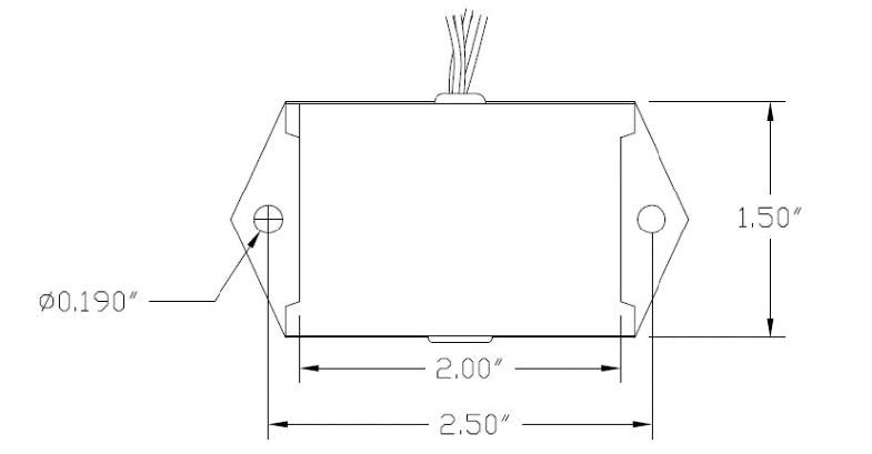
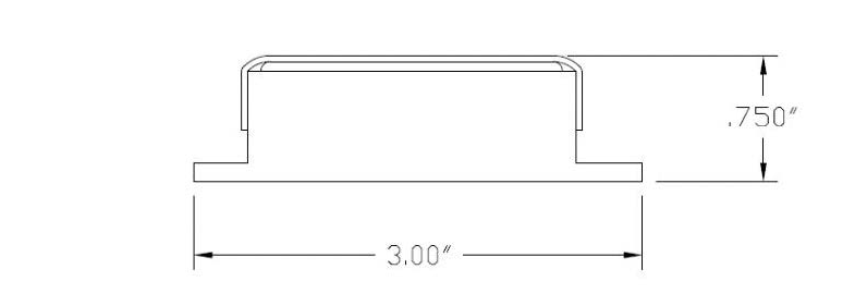
1.3 Physical Specifications
| Gehäuse | ABD Plastic |
| Länge | 51 mm (2.00″) |
| Breite | 38 mm (1,50″) |
| Höhe | 19 mm (0.75″) |
| Kabellänge | 46 cm (18″) |
| Bohrung Mitte | 64 mm (2.50″) |
| Loch-Durchmesser | 5 mm (0.19″) |
| Gewicht | 40 g |
1.4 Part Numbers
| Beschreibung | Teilenummer | |
| ±45° Range, ±0.1° Repeatability Tilt Switch (Open When Tripped) | 0729-1757-99 | Buy Now |
| ±45° Range, ±0.1° Repeatability Tilt Switch (Closed When Tripped) | 0729-1758-99 | Buy Now |
1.5 Related Products
| Beschreibung | Teilenummer | |
| ±35° Range, ±0.1° Repeatability Tilt Switch (Relay) | 0729-1736-99 | Buy Now |
Click here to see our entire collection of tilt switches and inclinometers.
2. Installation
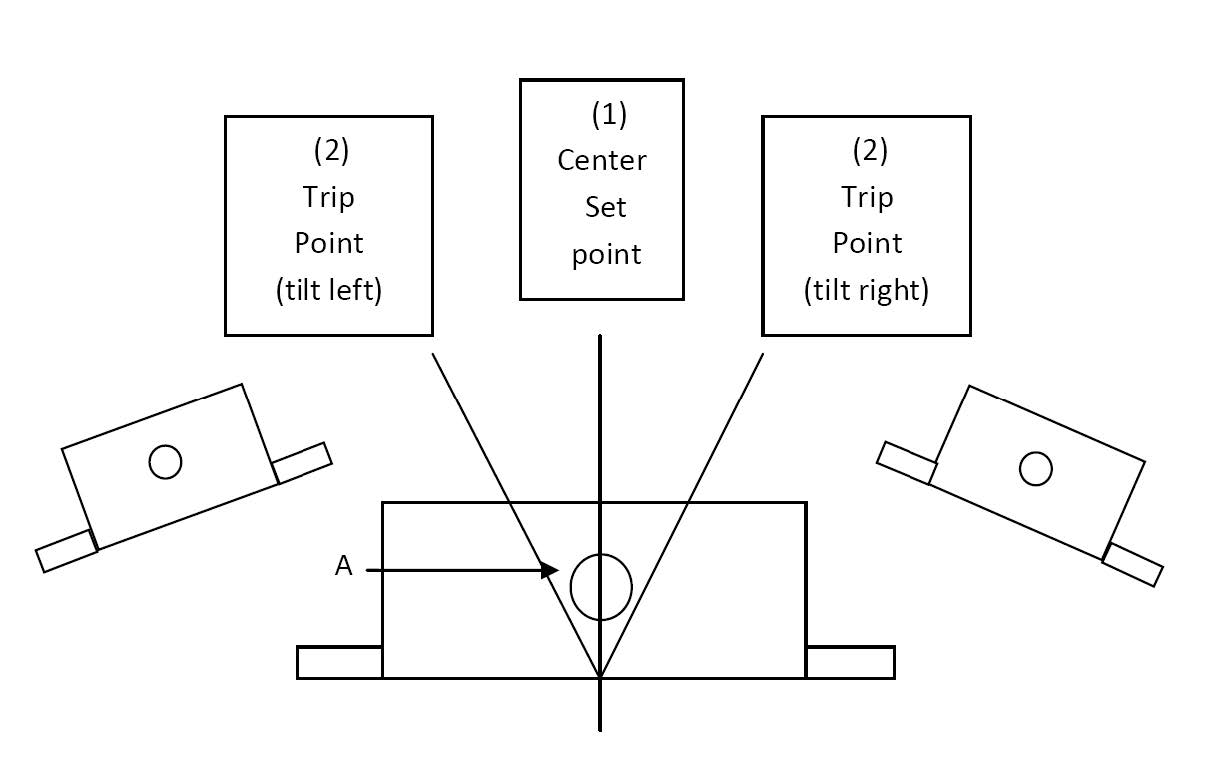
2.1 Direction of Measurement
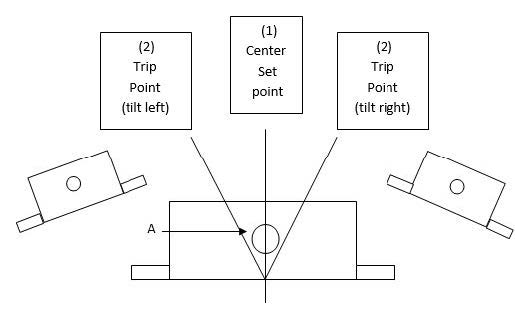
2.2 Mounting
The tilt switch must be mounted horizontally (parallel to the surface of the earth and perpendicular to the force of gravity). For best performance, mount the unit in a manner that it will be isolated from vibrations.
2.3 Electrical Connections
| Wire Color | Signal Name | Direction | Beschreibung |
| Rot | Vcc | Input | Supply Voltage Input: +4.5 V DC to +28 V DC Regulated |
| Schwarz | GND | - – | Boden |
| Grün | C | Input | Ground (Open Collector) |
| Blau | L | Ausgang | Left Trip Point Open Collector |
| Gray | R | Ausgang | Right Trip Point Open Collector |
| Orange | - – | - – | Zero Wire (potted units only) |
| Braun | - – | - – | Zero Wire (potted units only) |
2.4 Open Collector Connection
The open collector has two possible states: closed and open. In the closed state, the collector is connected to ground. This state can be considered the on state. In the open state, the collector is disconnected from ground. In this state, the connection is floating, and no current will flow. This can be considered the off state. Circuit analogies of these states are shown below.
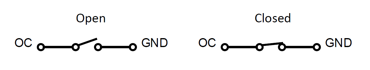
The behavior of the open collector is determined by the part number. The 0729-1757-99 is closed when not tripped and open when tripped. The 0729-1758-99 is reversed, so it is open when not tripped and closed when tripped.
2.5 Open Collector Wiring
Below is an example of how the open collector can be used in a circuit. This example will control two LEDs, one for each trip direction.
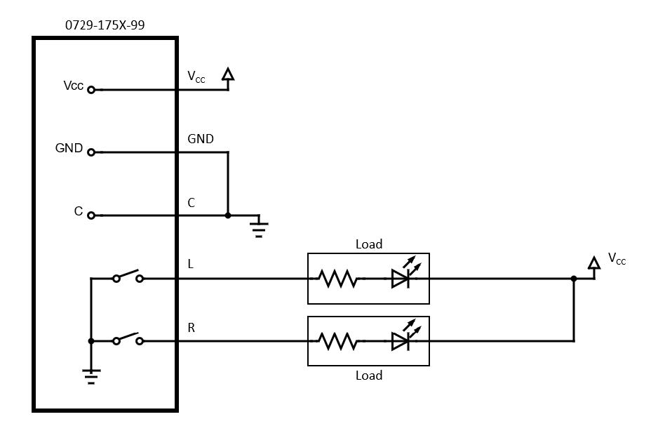
Note that this circuit will have different functionality depending on which tilt switch is used:
- An 0729-1757-99 will have the LEDs on normally. If the switch I tilted past the trip point in the left (L) or right (R) direction, the LED for that direction will turn off.
- An 0729-1758-99 will start with the LEDs off. When the switch is tilted past the trip point, the LED for that direction will turn on.
3. Set Trip Angle
3.1 For Non-Potted Units
- Remove the cap form the front of the unit.
- With no power applied, insert a jumper into the hole to shorting the 2 pins inside the unit.
- Tilt the sensor to the desired zero position. This can be any angle within the switch’s range. This will be the center of the non-trip angle range.
- Apply power and wait at least 3 seconds.
- Tilt the sensor to the desired trip angle, remove the jumper, and wait at least 3 seconds. The direction can be in either to the left (L) or right (R).
- Remove power from the unit and replace the cap.
- The unit is now programmed. The trip angle in the opposite direction (set using the above steps) is the same distance (symmetrical) from the zero position in the opposite direction. The unit can be reprogrammed as many times as needed to change the trip positions.
3.2 For Potted Units
- With no power applied, connect the orange and brown wires together.
- Tilt the sensor to the desired zero position. This can be any angle within the switch’s range. This will be the center of the non-trip angle range.
- Apply power and wait at least 3 seconds.
- Tilt the sensor to the desired trip angle, disconnect the orange and brown wires, and wait at least 3 seconds. The direction can be in either to the left (L) or right (R).
- Remove power from the unit.
- The unit is now programmed. The trip angle in the opposite direction (set using the above steps) is the same distance (symmetrical) from the zero position in the opposite direction. The unit can be reprogrammed as many times as needed to change the trip positions.