



1 Description
This application note explains the process for changing the MM200 Vacuum Controller analog output settings from a Windows PC.
The recommended method is to use The Fredericks Company Online Serial Terminal. The Online Serial Terminal communicates directly with the MM200 through a supported web browser and allows MM200 serial commands to be sent without installing additional communications software.
A USB-to-RS-232 converter is required to connect the MM200 to your computer.
Alternatively, the analog output settings can be changed using the Tera Term serial communications program. Tera Term must be installed on your computer before following these instructions. Download the latest version of Tera Term from GitHub .
Back to Table of ContentsIMPORTANT
The MM200 must have the 2-6200-213 RS-232/485 Communications Module installed to complete this procedure.
2 Required Equipment, Tools, and Software
| Equipment/Tool | Part Number/Requirement |
|---|---|
| MM200真空控制器 | 2-7900-20 |
| RS-232/485通信模块 | 2-6200-213 - must be installed in the MM200 |
| Windows PC | PC with an available USB port |
| USB-to-RS-232 Converter |
USB-A to DB9 RS-232 converter |
| DB9-to-DB9 Serial Cable |
DB9 male-to-female, straight-through cable |
| Google Chrome or Microsoft Edge | Online Serial Terminal method |
| Tera Term | Manual method only |
IMPORTANT
The DB9 cable must be a straight-through cable, with each pin connected to the corresponding pin at the opposite end. Do not use a null-modem or crossover cable.
3 Finding the COM Port
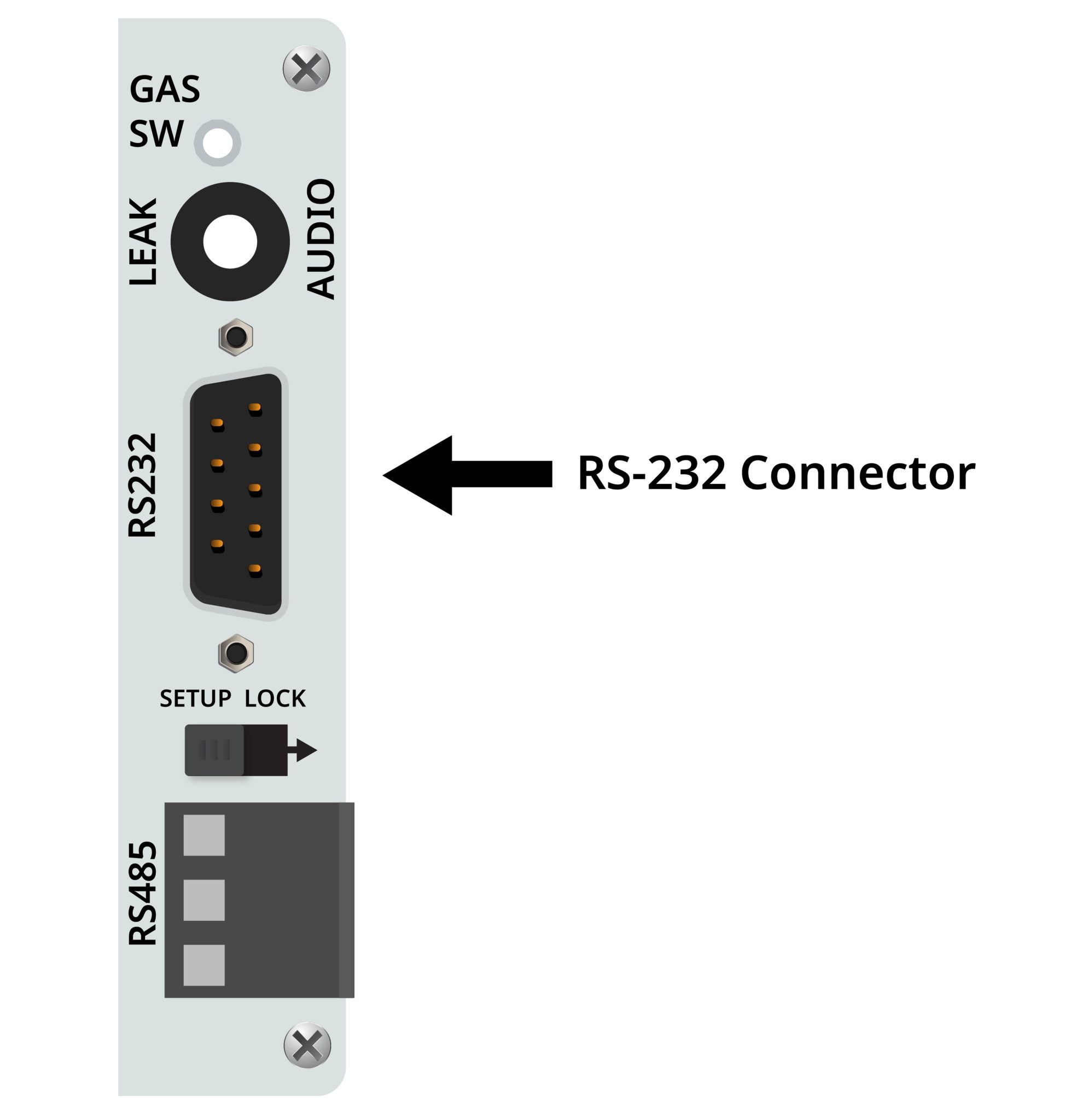
Verify that the MM200 has the RS-232/485 Communications Module (PN: 2-6200-213) installed.
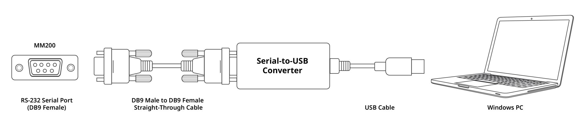
Connect the MM200 to your Windows PC as shown below:
- Connect the DB9 straight-through serial cable to the RS-232 connection on the MM200.
- Connect the other end of the DB9 cable to the USB-to-RS-232 converter.
- Connect the USB-to-RS-232 converter to an available USB port on your Windows PC.
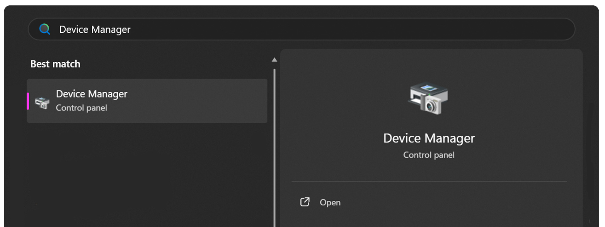
Open the Start Menu on your Windows PC.

Open Device Manager.
Expand the Ports (COM & LPT) dropdown.
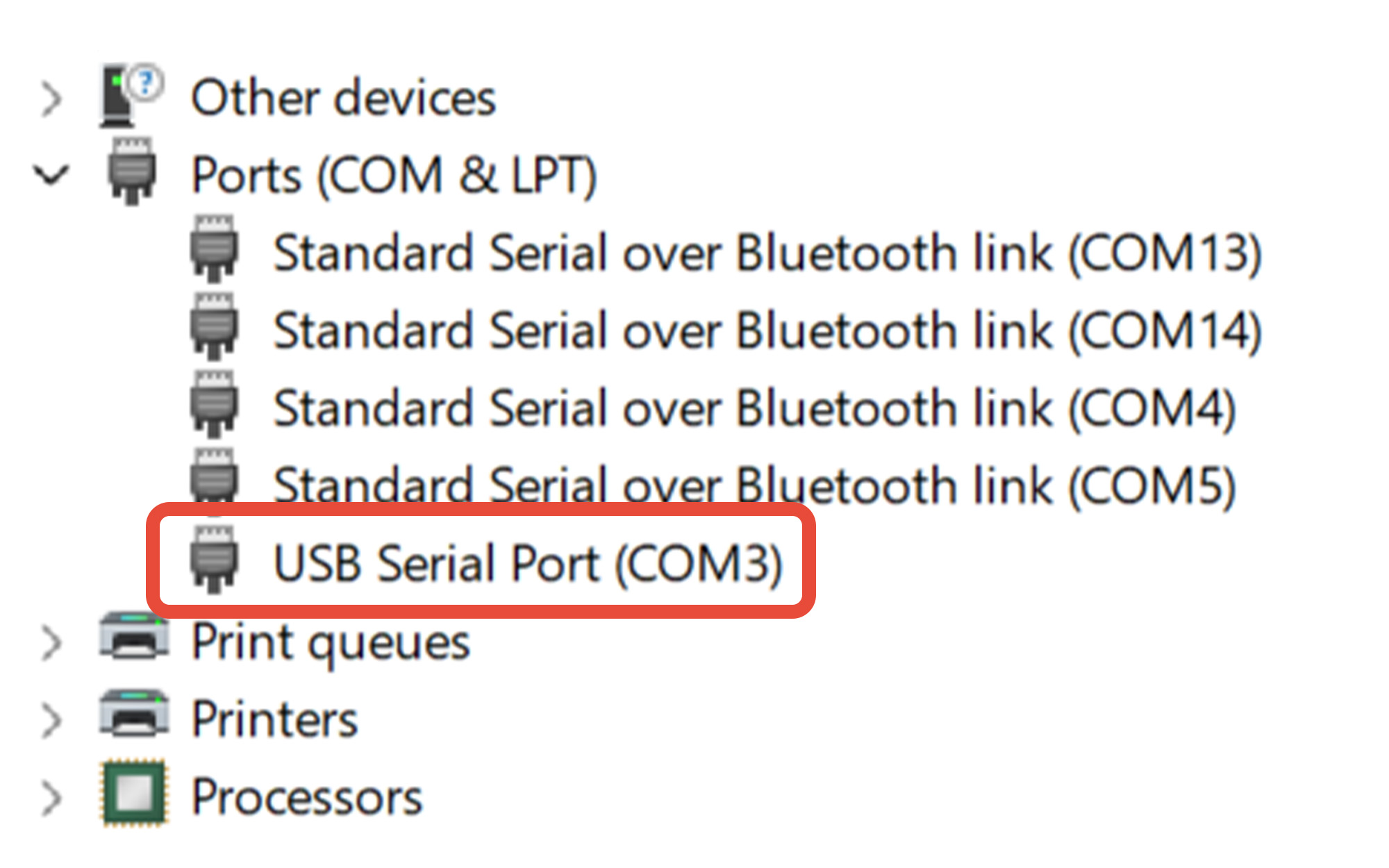
Determine the COM port assignment for your USB-to-RS-232 converter. In this example, the converter is assigned to COM3.
If you're unsure which COM port belongs to the USB-to-RS-232 converter:
- Leave Device Manager open.
- Unplug the USB-to-RS-232 converter from the PC.
- Watch which COM port disappears from the Ports (COM & LPT) list.
- Plug the converter back into the PC.
- The COM port that reappears is the port assigned to the USB-to-RS-232 converter.
Remember this COM port number. You will select it when connecting to the MM200 using either the Online Serial Terminal or Tera Term.
4 Using The Fredericks Company Online Serial Terminal
Using Google Chrome or Microsoft Edge, visit The Fredericks Company Online Serial Terminal .
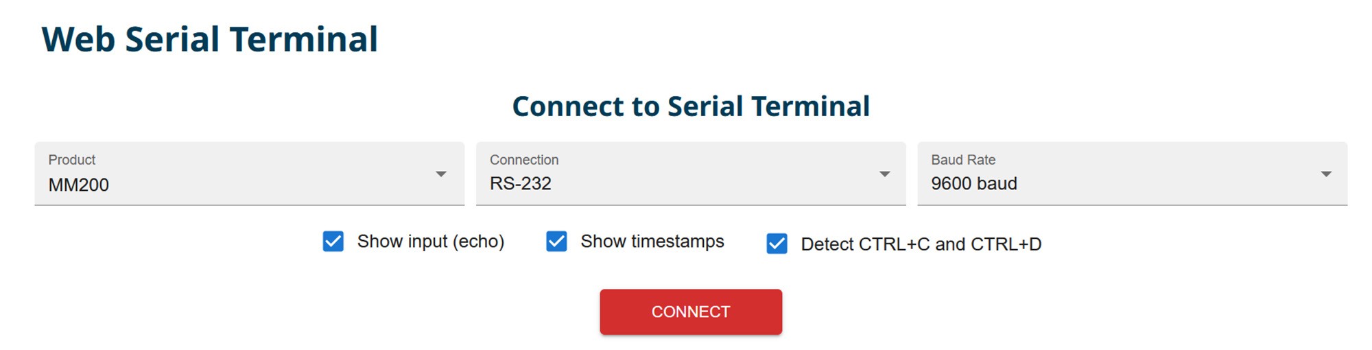
Select MM200 from the Product dropdown and RS-232 from the Connection dropdown. Select the baud rate configured on your MM200. In this example, 9600 baud is used.
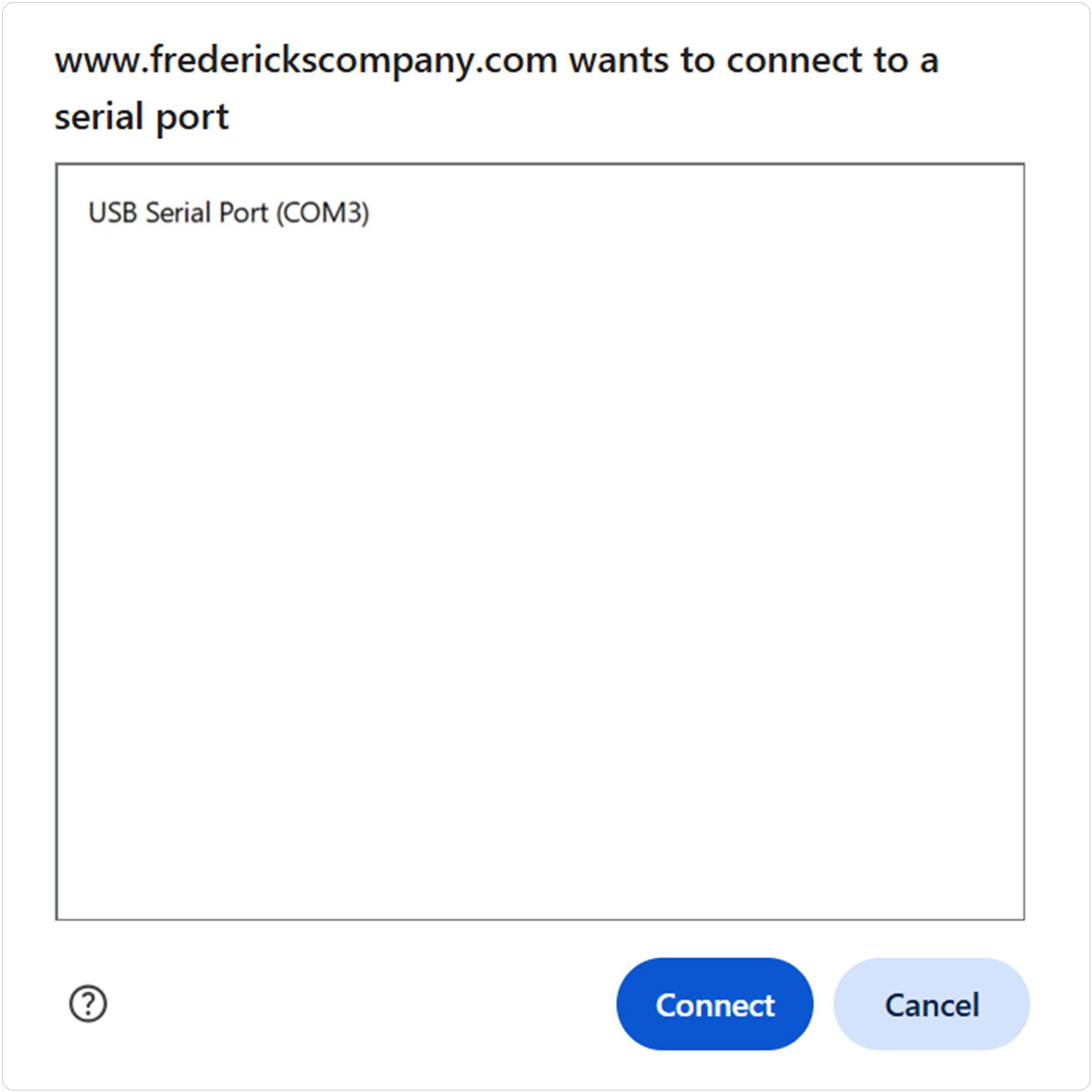
Click CONNECT to open the serial-port selection window.
Select the COM port assigned to your USB-to-RS-232 converter, then click Connect.
If you are unsure which COM port to select, see Section 3, Finding the COM Port.
If the MM200 is operating in Burst Mode:
Send: BF
The BF command exits Burst Mode and returns the MM200 to normal communications mode.
Use the Online Serial Terminal to send the analog output command for the installed vacuum gauge.
For example, to configure a 7B Cold Cathode Vacuum Gauge for the Linear analog output:
Send: R7BN
See Section 6, MM200 Analog Output Commands for the available commands.
Save the new analog output.
Send: SE
If the MM200 was operating in Burst Mode before you changed the analog output settings:
Send: BN
The BN command places the MM200 back into Burst Mode.
Repeat the procedure for any additional vacuum gauges whose analog output settings need to be changed.
If you continue to experience issues, start an online chat with us or contact our Technical Support Team .
IMPORTANT
After changing an analog output format, the SE command must be sent to save the new setting. If the setting is not stored, it will be lost when power to the MM200 is interrupted.
5 Using Tera Term
Open Tera Term on your Windows PC.
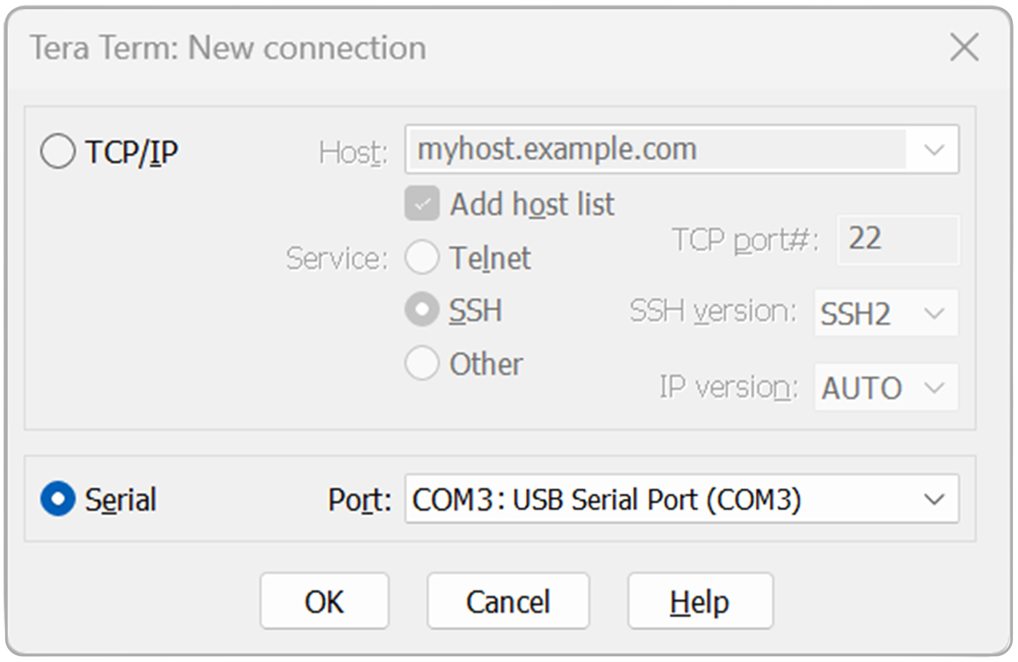
Select Serial, then select the COM port assigned to your USB-to-RS-232 converter from the Port dropdown.
Click OK to continue.
If you are unsure which COM port to select, see Section 3, Finding the COM Port.
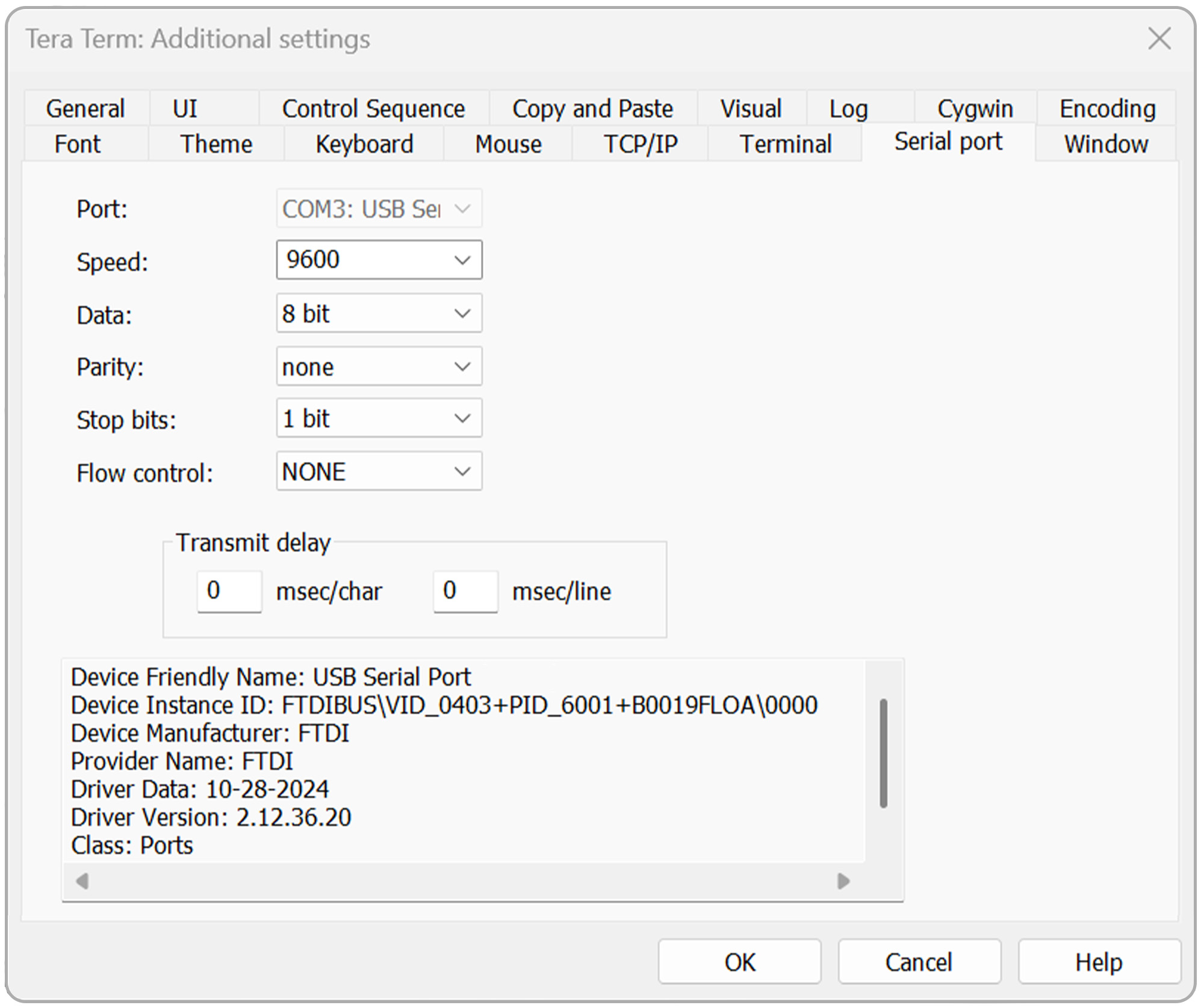
Open the Setup menu, then select Serial port.
Verify that the serial port settings are configured as follows:
- Baud rate: 9600
- Data: 8 bit
- Parity: none
- Stop: 1 bit
- Flow control: none
- Transmit delay: 0 msec/char, 0 msec/line
Click OK to continue.
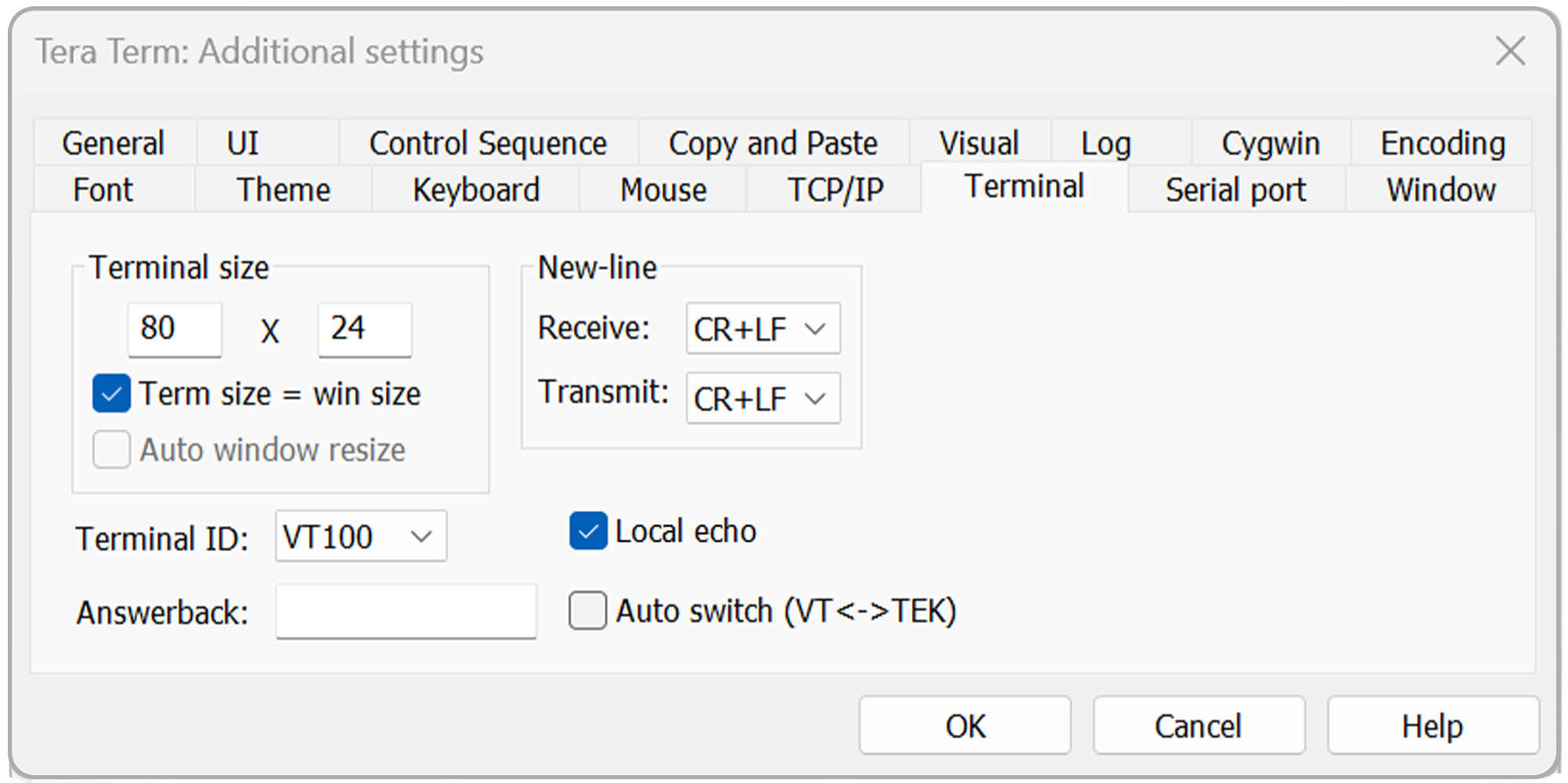
Open the Setup menu again, then select Terminal.
Under the New-line settings, configure the following:
- Receive: CR+LF
- Transmit: CR+LF
- Local echo: Checked
Click OK to continue.
If the MM200 is operating in Burst Mode:
Send: BF
The BF command exits Burst Mode and returns the MM200 to normal communications mode.
Use Tera Term to send the analog output command for the installed vacuum gauge.
For example, to configure a 7B Cold Cathode Vacuum Gauge for the Linear analog output:
Send: R7BN
See Section 6, MM200 Analog Output Commands for the available commands.
Save the new analog output.
Send: SE
If the MM200 was operating in Burst Mode before you changed the analog output settings:
Send: BN
The BN command places the MM200 back into Burst Mode.
Repeat the procedure for any additional vacuum gauges whose analog output settings need to be changed.
If you continue to experience issues, start an online chat with us or contact our Technical Support Team .
IMPORTANT
After changing an analog output format, the SE command must be sent to save the new setting. If the setting is not stored, it will be lost when power to the MM200 is interrupted.
6 MM200 Analog Output Commands
| 传感器 | 指挥部 | 名称 | 范围(托尔) | 五/司 | 说明 |
|---|---|---|---|---|---|
| 1E/F | R1EN | 直线型 | 1/100至1000/10,000 | 0至10V | 10 V = 1000/10,000 Torr |
| 1E/F | R1EM | 线性/十年 | 1/100至1000/10,000 | 2.00伏特/十年 | 10 V = 1000/10,000 Torr |
| 1E/F | R1EL | 对数 | 1/100至1000/10,000 | 3.33伏特/十年 | 10 V = 1000/10,000 Torr |
| 2A | R2AN | 直线型 | 10-3比1 | 0至10V | 10 V = 1 Torr |
| 2A | R2AL | 对数 | 10-3比1 | 3.33伏特/十年 | 10 V = 1 Torr |
| 2A | R2AT | 传统的 | 10-3至20 | 0至10V | 10V=10-3托尔 |
| 2A | R2AR | 线性修订版 | 10-3比1 | 0至10V | 10V=10-3托尔 |
| 3F | R3FM | 线性/十年 | 10-11至10-2 | 1.00伏特/十年 | 10 V = 10-2Torr |
| 3F | R3FL | 对数 | 10-11至10-2 | 1.00伏特/十年 | 10 V = 10-2Torr |
| 3F | R3Fx | 直线型 | 10-2至10-x | 0至10V | 10 V = 10-8<-x<-2 Torr |
| 4A | R4AN | 线性/十年 | 10-3至1 000 | 1.00伏特/十年 | 10 V = 1000 Torr |
| 4A | R4AU | 直线型 | 10-3比1 | 0至10V | 10 V = 1 Torr |
| 4A | R4AT | 直线型 | 10-3至10 | 0至10V | 10 V = 10 Torr |
| 4A | R4AL | 对数 | 10-3至1 000 | 1.67伏特/十年 | 10 V = 1000 Torr |
| 5A/B/C/D/E/F | R5AN | 直线型 | 全比例 | 0至10V | 10 V = 满刻度 |
| 5A/B/C/D/E/F | R5AL | 对数 | 3个十年 | 3.33伏特/十年 | 10 V = 满刻度 |
| 7B | R7BM | 线性/十年 | 10-7 to 10-3 | 2.00伏特/十年 | 10V=10-3托尔 |
| 7B | R7BL | 对数 | 10-6 to 10-3 | 3.33伏特/十年 | 10V=10-3托尔 |
| 7B | R7BE | 扩展对数 | 10-7 to 10-3 | 2.50 V/Decade | 10V=10-3托尔 |
| 7B | R7BN | 直线型 | 10-6 to 10-3 | 0至10V | 10V=10-3托尔 |
| 7B | R7BT | 传统的 | 10-7 to 10-3 | 0至10V | 10V=10-3托尔 |
| 7E | R7EM | 线性/十年 | 10-8 to 10-2 | 1.00伏特/十年 | 10 V = 10-2Torr (4-10 V) |
| 7E | R7EL | 对数 | 10-8 to 10-2 | 1.67伏特/十年 | 10 V = 10-2Torr |
| 7E | R7Fx | 直线型 | 10-2至10-x | 0至10V | 10 V = 10-7<-x<-2 Torr |
| 7F/FC/FCS | R7FM | 线性/十年 | 10-11至10-2 | 1.00伏特/十年 | 9V=10-2托尔 |
| 7F/FC/FCS | R7FL | 对数 | 10-11至10-2 | 1.00伏特/十年 | 9V=10-2托尔 |
| 7F/FC/FCS | R7x | 直线型 | 10-2至10-x | 0至10V | 10 V = 10-8<-x<-2 Torr |