


1. Product Information
1.1 Description
The RS-485 signal conditioner utilizes Fredericks single and dual axis electrolytic tilt sensors. The signal conditioner provides the necessary excitation to the sensor and signal conditioning of the output to communicate over an RS-485 interface.
The standard industrial RS-485 interface enables long transmission distances and the option to connect multiple modules, with individual addresses, to the same bus. In addition to tilt angle, temperature information is also available from the module that can be used for temperature compensation of the sensor.
Since 1935, Fredericks has been a global provider and U.S. manufacturer of high-performance tilt measurement products. Built to last, our products are made with state-of-the-art sensing technology, proven processes, and an intrinsic passion for the trade. Offering simple integration and quality and safety benchmarks, our customers benefit not just from standard-setting reliability, but from our commitment to competitive pricing and performance.
1.2 Operating Specifications
| 통신 | RS-485 |
| 아날로그 입력 해상도 | 16비트(10비트 오버샘플링) |
| 운영 범위 | 센서 범위의 0%에서 100% |
| 공급 전압 | 3.3V DC ~ 5V DC |
| 공급 전류 | 9mA @ 5V DC, 6mA @ 3.3V DC |
| 작동 온도 | -40°C ~ 85°C |
| 보관 온도 | -40°C ~ 125°C |
| 제어되는 센서 | 1 또는 2 |
| 측정 축 | 1 또는 2 |
| 온도 센서 범위 | -40°C ~ 125°C |
1.3 Physical Specifications
| 무게 | 4 g |
| 길이 | 32 mm (1.25″) |
| 너비 | 32 mm (1.25″) |
| 홀 센터 | 27 mm (1.05″) |
| 구멍 직경 | 2.25 mm (0.089″) |
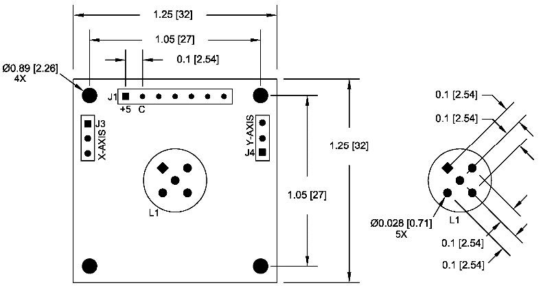
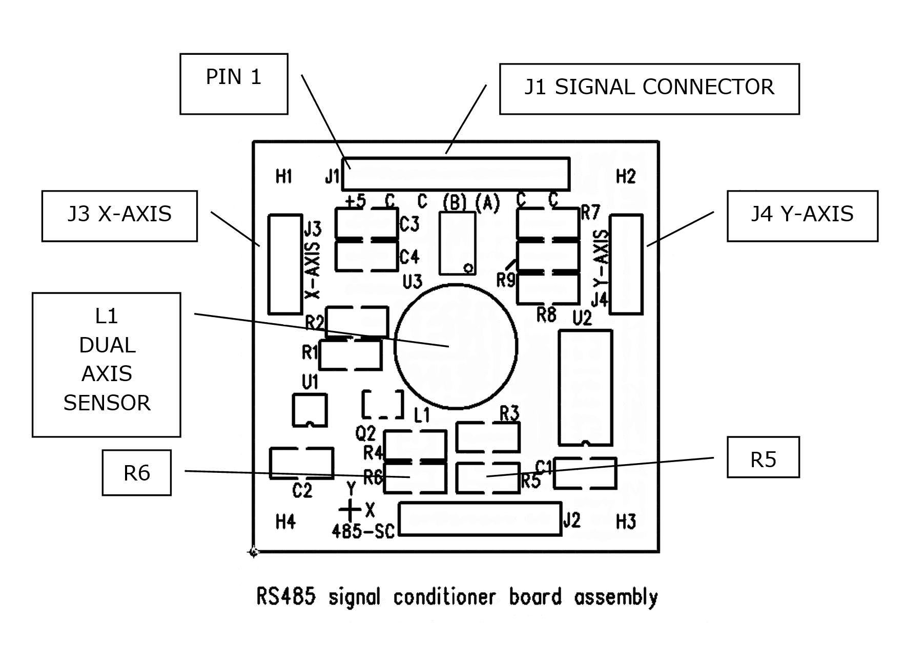
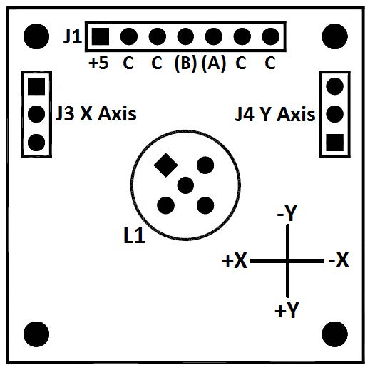
1.4 Board Layout
1.5 Compatible Sensors
| 부품 번호 | 축 | 운영 범위 | 선형 범위 | 반복성 | |
| 0717-4318-99 | 2 | ±60° | ±25° | ±0.1° | Buy Now |
| 0717-4319-99 | 2 | ±50° | ±20° | ±0.1° | Buy Now |
| 0717-4313-99 | 2 | ±50° | ±20° | ±0.05° | Buy Now |
| 0717-4315-99 | 2 | ±60° | ±25° | ±0.05° | Buy Now |
| 0703-0711-99 | 2 | ±3° | ±1° | ±0.001° | Buy Now |
| 0703-1602-99 | 1 | ±25° | ±10° | ±0.005° | Buy Now |
| 0737-0101-99 | 1 | ±10° | ±5° | ±0.0006° | Buy Now |
| 0703-1203-99 | 1 | ±0.5° | ±0.15° | ±0.0003° | Buy Now |
| 0711-0763-99 | 1 | ±1° | ±0.25° | ±0.0008° | Buy Now |
| 0711-0768-99 | 1 | ±3° | ±0.25° | ±0.0008° | Buy Now |
| 0719-3705-99 | 1 | ±10° | ±5° | ±0.0006° | Buy Now |
| 0719-3703-99 | 1 | ±0.5° | ±0.15° | ±0.0003° | Buy Now |
| 0719-1138-99 | 1 | ±1° | ±0.25° | ±0.0008° | Buy Now |
| 0719-1143-99 | 1 | ±3° | ±0.25° | ±0.0008° | Buy Now |
Other Fredericks Company electrolytic tilt sensors will also be compatible. Click here to view the complete list.
1.6 Related Products
Click here to see our entire collection of tilt sensors and inclinometers.
2. Installation
2.1 Mounting
The board is mounted in a horizontal position when a sensor is installed into the board. If external single axis sensors are connected with wires, then the board can be mounted in any position.
2.2 Electrical Connections
| Pin Label | Signal Name | 설명 |
| +5 | VCC | Supply voltage input: +3 to +5 V DC regulated |
| C | GND | Ground – Reference for the digital signals and supply voltage |
| C | GND | Ground – Reference for the digital signals and supply voltage |
| B | TX | RS-485 B |
| A | RX | RS-485 A |
| C | GND | Ground – Reference for the digital signals and supply voltage |
| C | GND | Ground – Reference for the digital signals and supply voltage |
| L1 | – | Connection for dual axis electrolytic sensor |
| J2 | – | Factory use only |
| J3 | – | Connection for single axis electrolytic sensor (X axis) |
| J4 | – | Connection for single axis electrolytic sensor (Y axis) |
2.3 Sensor Connection
The 1-6200-008 signal conditioner can be configured to operate one dual axis sensor or two single axis sensors. This configuration is determined by the resistor values of R5 and R6.
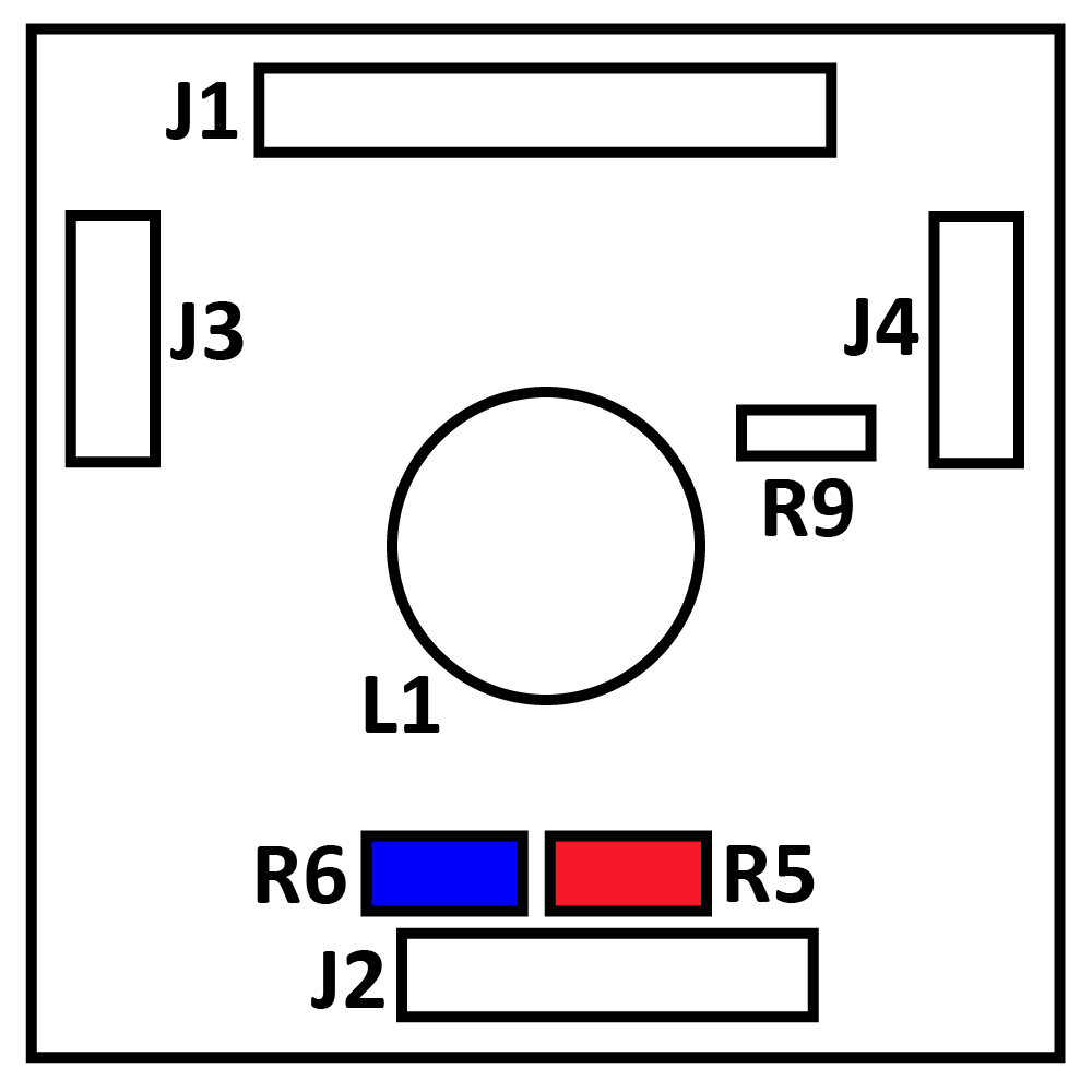
For a dual axis sensor: R5 is 10 kΩ, R6 is not installed (open), sensor is connected to L1.
For single axis sensors: R5 is not installed (open), R6 is 1kΩ, and sensor(s) are connected to J3 and/or J4.
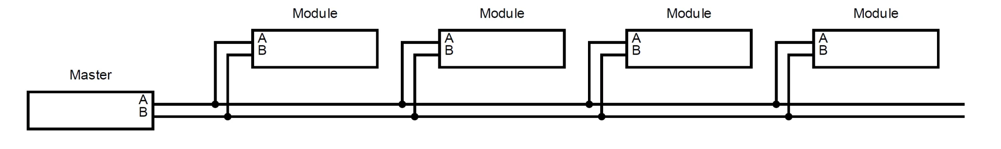
2.4 Data Bus Connections
Before connecting the modules to the bus, make sure they all have different addresses (see 3.2 Setup Commands). Connect the ‘A’ pins of each module and the ‘B’ pins of each module. Up to 32 modules can be connected on a single bus. If communication fails to connect, switch A and B at the master end.
2.5 RS-485 Communication Settings
For communication, use software such as Tera Term or Microsoft Hyper-Terminal (included with Windows 8 and earlier). The following parameters are the factory defaults, but some can be changed later.
| Setting | Value | Comments |
| 전송 속도 | 9600 (factory default) | Settable from 1200 to 38400 |
| 데이터 비트 | 8 | Fixed |
| 패리티 | 없음 | Fixed |
| 비트 중지 | 1 | Fixed |
| 주소 | 99 | Settable from 01 to 99 |
3. Commands
3.1 Data Commands
The following is the command format to read the sensor output and board temperature.
*XXYY#: * = start of command, XX = address, YY = command, # = end of command
| 설명 | 명령 | Output* |
| X Axis Data | *XX11# | ACSII (16-bit) |
| Y Axis Data | *XX21# | ACSII (16-bit) |
| Board Temperature | *XX41# | ACSII (10-bit) |
*All responses are terminated with newline and carriage return characters
The board’s MCP9700 temperature sensor will return a raw 10-bit value. Use the following equations to convert this to temperature:

3.2 Configuration Commands
| Command* | 설명 | 출력 |
| *9980# | 제품 정보 읽기 | Fredericks RS485 signal conditioner Ver X.X |
| *9981Axx# | Change address (xx = new address, 01 to 99) | Returns new address |
| *9982Sxxxxxxxxxxxx# | Enter user information X must be exactly 12 characters Alphanumeric, ‘-‘ and space are allowed |
Returns ID |
| *9982D# | 사용자 정보 읽기 | Returns user information |
| *9984Z# | Zero unit to current position (Ver 2.0 only) | Zeroing |
| *9984R# | Reset zero and clear offset | Resetting zero |
| *9988Rx# | Change baud rate X = code for new baud rate 1 = 1200 2 = 2400 3 = 4800 4 = 9600 (default) 5 = 19200 6 = 38400 |
없음 |
| *9989B# | reset to factory defaults Address = 99 Baud rate = 9600 |
없음 |
*All commands assume address 99
3.3 Restore Factory Defaults
In addition to the reset command that can be used, there is a hardware reset that can be used if the baud rate or address are unknown. This is done by placing a short on R9 on the PCB before powering the unit. After power is applied, remove power and short. This will reset the unit to default values. Refer to 1.4 Electrical Connections & Board Layout for R9 location.