


1 Introduction
1.1 Disclaimer
All information in this manual is subject to change without notice. The Fredericks Company assumes no responsibility for inaccuracies in product specifications or any liability arising from product use. Please contact us online or call +1 215 947 2500 with comments or questions.
1.2 Description
The MX2A is a thermocouple vacuum gauge with a range of 1*10-4 Torr to 1000 Torr. It utilizes a Televac® 2A Thermocouple Vacuum Gauge. It has a two color OLED display with selectable units of Torr, Millibar, and Kilopascal. Settings can be changed through RS-485 communications with a PC or on the unit using four capacitive touch buttons located on the top of the unit. The MX2A has 2 set points, one relay and one open collector, and a selectable analog output option. The analog output has a variety of options including four linear outputs, linear by decade, logarithmic, and non-linear.
1.3 Operating Specifications
| 운영 범위 | 1*10-4 토르 ~ 1000 토르 |
| 통신 | RS-485 |
| 아날로그 출력 | 7개의 선택 가능한 0 V DC ~ 10 V DC |
| 프로그래밍 가능한 집합 점 | 2 |
| 세트 포인트 1 | 컬렉터 열기 |
| 세트 포인트 2 | 릴레이 |
| 공급 전압 | 22V DC ~ 26V DC |
| 최대 전력 | 8 W |
| 교정 매체 | 건조한 공기 또는 질소 |
| 압 | 150 psi |
| 디지털 출력 해상도 | 지수가 있는 2개의 중요한 숫자 |
| 아날로그 출력 해상도 | 16 비트 |
| 작동 온도 | 0°C ~ 50°C |
| 베이크아웃 온도 | |
| 황동(PN: 2-8910-110) | 100 °C (전자 제품 제거) |
| 스테인리스 스틸(PN: 기타 모든 제품) | 200 °C (전자 제품 제거) |
| 응답 시간 | ≤2 s |
| 판독 가능한 거리 표시 | 3m(10피트) |
| 정확도 | |
| 0.1 mTorr ~ 1mTorr | 0.1 mTorr 해상도 |
| 1 mTorr ~ 10 mTorr | ±1 mTorr |
| 10m토르 ~ 1토르 | ±10% 판독 |
| 1 토르 ~ 100 토르 | 판독값 ±30(수직 마운트) |
| 100 토르 ~ 1000 토르 | ±10% 판독(수직 마운트) |
| 아날로그 출력 | ±10mV |
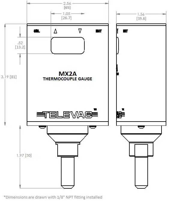
1.4 Dimensions
1.5 Safety Information
START BY READING THESE IMPORTANT SAFETY INSTRUCTIONS AND NOTES
In these instructions the word “product” refers to the MX2A and all of its approved parts and accessories. NOTE: These instructions do not and cannot provide for every contingency that may arise in connection with the installation, operation, or maintenance of this product. Should you require further assistance, contact us online or call +1 215 947 2500.
This product has been designed and tested to offer reasonably safe service provided it is installed, operated, and serviced in strict accordance with these safety instructions.
These safety precautions must be observed during all phases of operation, installation, and service of this product. Failure to comply with these precautions or with specific warnings elsewhere in this manual violates safety standards of design, manufacture, and intended use of the instrument. Televac® disclaims all liability for the customer’s failure to comply with these requirements. for the customer’s failure to comply with these requirements.
- Read Instructions Read all safety and operating instructions before operating the product.
- Retain Instructions Retain the safety and operating instructions for future reference.
- Heed Warning Adhere to all warnings on the product and in the operating instructions.
- Follow Instructions Follow all operating and maintenance instructions.
- Accessories: Do not use accessories not recommended in this manual as they may require a technician to restore the product to its normal operation.
The MX2A qualifies as a Safety Extra-Low Voltage (SELV) device. As such, it represents little to no hazard concerning electrical shock or burns.
Do not substitute parts or modify instrument. Because of the danger of introducing additional hazards, do not install substitute parts or perform any unauthorized modifications to the product. Return the product to Televac® for service and repair to ensure that safety features are maintained. Do not use this product if it has unauthorized modifications.
The MX2A is not designed to be serviced by the operator. Any service should be done by a Televac® technician. However, in the event of any attempt to service the unit, please remove the power supply to minimize the risk of harm.
The 2A sensor is user-replaceable and additional 2A sensors can be ordered from Televac® by the operator. Do not attempt to use other sensors with the MX2A remote. Using another sensor may result in damage to the MX2A and voids any warranty in place.
2 Setup
2.1 Installation
Each MX2A is designed to be used in conjunction with a 2A sensor. The 2A sensor can be mounted in any orientation for accurate measurement up to 10 Torr. For measurements up to atmosphere, mount the 2A sensor in an upright position. The sensor should be mounted close to the area where vacuum measurement is desired. Failure to mount the 2A sensor in a vertical position will decrease the accuracy of the measurement between 10 Torr and atmosphere, but will leave the accuracy below 10 Torr unaffected. Each 2A sensor has a key that only allows the MX2A to mate with the sensor in the proper orientation. Rotate the MX2A until the correct alignment is obtained and the MX2A is able to slide onto the 2A sensor. Connect the power connector to the top of the unit and be sure to tighten the screws so that a firm connection is maintained.
Try to avoid connecting the MX2A to the vacuum chamber by long or narrow piping as this may affect the accuracy and response time of the unit. Avoid mounting the unit near a heater within the chamber as this may affect the measurement accuracy. Excessive vibration of the unit may affect accuracy and decrease the life of the unit. Exposure to oils and other contaminants will decrease the accuracy and decrease the life of the sensor. Do not expose the unit to corrosive gases.
2.2 Electrical Information
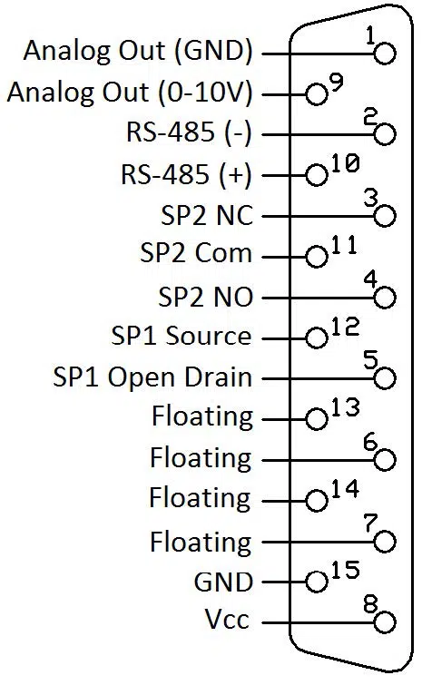
Power connectors and adaptors for use with the MX2A are available for purchase from Televac®. Operators wishing to create their own adaptors should refer to the pin out of the MX2A below. Each connection labeled “Floating” has no connection and should remain so.
| 핀 | 설명 |
| 1 | Analog Output (Ground) |
| 2 | RS-485 (-) |
| 3 | SP2 NC |
| 4 | SP2 NO |
| 5 | SP1 오픈 드레인 |
| 6 | 플로팅 |
| 7 | 플로팅 |
| 8 | 공급 전압 |
| 9 | Analog Output (0 to 10 V) |
| 10 | RS-485 (+) |
| 11 | SP2 Com |
| 12 | SP1 소스 |
| 13 | 플로팅 |
| 14 | 플로팅 |
| 15 | Ground |
2.3 Menu Navigation
The MX2A contains many operator customizable features. Changing these features is possible through the menu or via RS-485 communications. To navigate the menu simply use the buttons found on top of the MX2A. The four buttons include the SEL button, an UP arrow, a DOWN arrow, and an ENT button. Using the SEL button allows the operator to change between menu categories. Using the ENT button allows the user to enable value editing and save values in addition to toggling between options where appropriate. Using the UP and DOWN arrows allows navigation through menu options. The UP and DOWN arrow buttons are also used to edit values.
2.4 Menu Structure
- Measurement
- 교정
- Vacuum
- 10 토르
- Atmosphere
- Resolution High/Low
- Default
- Diagnostic
- Analog Output Adjustment
- 가스 유형
- 포인트 설정
- SP1L
- SP1H
- SP2L
- SP2H
- Units
- Torr/kPa/mbar
- 출력
- 아날로그 출력
- 로그
- Linear by Decade
- 비선형
- 선형 4
- 선형 3
- 선형 2
- 선형 1
- RS-485 I/O
- 주소
- 패리티
- 비트 중지
- 전송 속도
- 아날로그 출력
2.5 Explanation of Menu Items and Navigation
Below is a general explanation of each level of the menu structure of the MX2A.
2.5.1 Measurement
The measurement screen contains the reading of the sensor in easy-to-read blue digits and includes units. In addition to the digital reading, the yellow bar on the measurement screen provides an analog indication of the pressure based on a logarithmic scale. At 1000 Torr the yellow bar should stretch across the width of the screen. At 0 Torr the yellow bar will disappear, and at 1 Torr, the yellow bar will be half way across the screen.
2.5.2 Calibration
To reach the calibration screen:
- Navigate to the measurement screen.
- Press SEL once.
- Press the UP and DOWN arrows to navigate between panes under the calibration heading
To ensure that the unit always displays with the most accuracy, the MX2A includes a number of operator configurable calibration points. While the MX2A is factory calibrated, the use of the included calibration points may become necessary after extended use, contamination, etc. If accuracy is critical, it is recommended to return the sensor to Televac® for ISO 17025 Accredited calibration or NIST-traceable calibration.
Note: Calibration should be performed in the following order: vacuum adjustment, 10 Torr adjustment, 760 Torr adjustment. Failing to calibrate in this order will result in inaccuracies.
Note 2: CHANGING CALIBRATION SETTINGS VOIDS NIST-TRACEABLE CALIBRATIONS AND ISO 17025 ACCREDITED CALIBRATIONS!
A. Vacuum (Zero)
To reach the vacuum screen:
- The vacuum screen is the first pane of the calibration screen.
- Press ENT to unlock the vacuum screen.
- Press UP or DOWN to adjust the reading
- When the desired reading is reached, press ENT to save and lock the change.
The vacuum calibration point allows the gauge to adjust the pressure reading at high vacuum (“zeroing”). This should be used only when the operator knows that the unit is pumping down below 10-4 Torr and the unit reads a non-zero number. When the vacuum is below the range of MX2A measurement (preferably as low as 10-5 Torr), adjust the unit until it blinks between .0000 and .0001.
For users calibrating against a NIST calibrated standard, maximum accuracy for the MX2A can be obtained by calibrating the MX2A to .0050 Torr instead of the normal .0000 Torr reading.
B. 10 Torr
To reach the 10 Torr adjustment screen:
- Navigate to the calibration screen.
- Press DOWN one time.
- Press ENT to unlock the 10 Torr adjustment screen.
- Press UP or DOWN to adjust the reading.
- When the desired reading is reached, press ENT to save and lock the change.
The 10 Torr calibration point allows the gauge to adjust the pressure reading at 10 Torr. This should be used only when the operator knows that the unit under calibration is compared to a reference gauge that is NIST traceable calibrated and reading near 10 Torr.
C. Atmosphere
To reach the atmosphere screen:
- Navigate to the calibration screen.
- Press DOWN two times.
- Press ENT to unlock the atmosphere adjustment screen.
- Press UP or DOWN to adjust the reading.
- When the desired reading is reached, press ENT to save and lock the change.
The atmosphere calibration point allows the gauge to adjust the pressure reading at atmosphere (760 Torr). This should be used only when the operator knows that the unit is exposed to atmosphere or is compared to a reference gauge that is NIST calibrated and reading near 760 Torr.
For users calibrating against a NIST calibrated standard, maximum accuracy for the MX2A can be achieved by adjusting the unit between 740 Torr and 780 Torr.
D. Resolution High/Low
To reach the resolution screen:
- Navigate to the calibration screen.
- Press DOWN three times.
- Press ENT to unlock the resolution high/low screen.
- Press UP or DOWN to adjust the reading.
- When the desired reading is reached, press ENT to save and lock the change.
The resolution of the MX2A is set to low by default. Under this setting the resolution is determined by the accuracy of the gauge. The gauge will automatically adjust the resolution based on the pressure. The MX2A always displays four digits on the calibration screen. For operators who are looking for more resolution on the measurement screen, the MX2A can be set to high resolution and will display four digits on the measurement screen.
E. Default
To reach the default screen:
- Navigate to the calibration screen.
- Press DOWN four times.
- Press ENT twice to trigger a reset to the factory defaults.
The default screen resets all calibration point adjustments to the default values. This feature should only be used when necessary. Warning: RESTORING TO DEFAULT CALIBRATION SETTINGS VOIDS THE CALIBRATION!
F. Diagnostic
To reach the diagnostic screen:
- Navigate to the calibration screen.
- Press DOWN five times.
The diagnostic screen is used by Televac® technicians when inspecting the MX2A for any problems. Under no circumstance does the operator need to access or consider this screen.
G. Analog Output Adjustment
To reach the analog output screen:
- Navigate to the calibration screen.
- Press DOWN six times.
- Press ENT to unlock the analog output adjustment screen.
- Press UP or DOWN to adjust the reading.
- When the desired reading is reached, press ENT to save and lock the change.
The analog output accuracy for the MX2A generally agrees with the digital reading. However, in extreme temperatures or in significant humidity, the agreement may change slightly. For uses of the MX2A where the analog output accuracy is critical, an adjustment is available to ensure accuracy. When making this adjustment use a calibrated voltmeter to measure the analog output voltage when the MX2A is at a very stable pressure. Compare this voltage reading to the expected voltage. The expected voltage can be determined based on the formulae in the section of this manual entitled Analog Output.
H. Gas Type
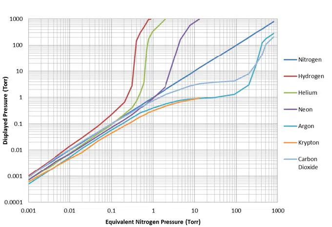
The 2A sensor exhibits different sensitivities to different gases. The default gas is set to air. Air and dry nitrogen are approximated to have the same sensitivity and using either does not require any compensation. For users who wish to measure the pressure of Argon gas, the MX2A includes an Argon correction option.
To change the MX2A between air/nitrogen and agron modes:
- Navigate to the calibration screen.
- Press DOWN seven times.
- Press ENT to unlock the gas type screen.
- Press UP or DOWN to change between the gas modes.
- When the appropriate mode is selected, press ENT to save and lock the change.
2.5.3 Set Points
To reach the set point screen:
- Navigate to the measurement screen.
- Press SEL two times.
- The set point screen contains set point 1 low.
- To access set point 1 high, set point 2 low, or set point 2 high, press DOWN from the initial set point screen.
- When the correct set point is selected, press ENT to unlock the set point adjustment screen.
- Press UP and DOWN to change the value.
- When the desired reading is reached, press ENT to save and lock the change.
The MX2A contains two set points for the convenience of the operator. Set point 1 is an N-Channel 60 V MOSFET open collector. It has a maximum current rating of 1 A. The data sheet can be found at www.vishay.com/docs/69958/si2308bds.pdf. Set point 2 is a relay with a maximum switching voltage of 220 V DC (250 V AC) and a maximum switching current of 2 A. The data sheet can be found at www.te.com/en/product-1393788-3.html.
2.5.4 Units
To reach the units screen:
- Navigate to the measurement screen.
- Press SEL three times.
- Press ENT to unlock the units screen.
- Press UP and DOWN to navigate between units.
- When the desired unit is reached, press ENT to save and lock the change.
Depending on the process or the region, the desired units for the MX2A may vary. To accommodate this need, the MX2A includes a unit adjustment feature. The MX2A can be set to display the units in Torr, kPa, or mbar.
2.5.5 Output
To reach the output screen:
- Navigate to the measurement screen.
- Press SEL four times.
- Press UP and DOWN to navigate between the analog output and RS-485 panes.
- When the desired field is present, press ENT to enter the heading.
The MX2A features a number of analog outputs and RS-485 digital output and input.
A. Analog Output
To toggle the analog output type:
- Navigate to the analog output screen.
- Press ENT to unlock the screen.
- Press UP or DOWN to set the desired output type.
- When the desired analog output is reached, press ENT to save and lock the change.
The types of analog output are listed below. For more information on the types of output, please see the heading in this manual labeled Analog Output.
- 로그
- Linear by Decade
- 비선형
- 선형 4
- 선형 3
- 선형 2
- 선형 1
B. RS-485 I/O
To make changes under the RS-485 I/O screen:
-
- Navigate to the RS-485 I/O screen.
- Press UP or DOWN to reach the desired RS-485 setting.
- Press ENT to unlock the setting.
- Press UP or DOWN to change the fields.
- Press ENT to save and lock the change.
The RS-485 settable fields are listed below. Please see the sections labeled RS-485 Communications and Changing Communications Parameters for more details and a complete list of commands. Listed below are the fields within the RS-485 I/O screen.
-
-
- 주소
- 전송 속도
- 비트 중지
- 패리티
-
2.6 Analog Output
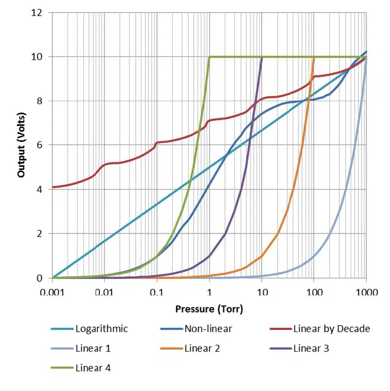
The MX2A provides the option for outputting the vacuum reading in an analog form. Operators who wish to use PLCs to monitor processes should find this function useful. There are seven different analog output formats to choose between. The formats include Logarithmic, Linear by Decade, Non-linear, Linear 4, Linear 3, Linear 2, and Linear 1.
A. Logarithmic
The Logarithmic output is the most useful and accurate output for covering the entire range of the 2A with an analog output. This format uses the formula below to convert the output voltage into a pressure measurement:
Pressure (Torr) = 10.6x(Voltage-5)
For example, a voltage reading of 3.075 Volts corresponds to pressure of .07 Torr.
10.6x(3.075-5) = 0.07 Torr
B. Linear by Decade
The Linear by decade output spans the entire range of the MX2A. It uses the units digit of the voltage reading to communicate the decade of the pressure reading and the units after the decimal to communicate the specific pressure using the very generalized expression below, where A, B, C, and D are digits ranging from 0-9:
Voltage = A.BCD → Pressure (Torr) = 10A-6 x .BCD
For example, a voltage reading of 8.367 Volts corresponds to a pressure of 36.7 Torr.
108-6 x .367 = 36.7 Torr
C. Non-Linear
The Non-linear option outputs the raw signal collected by the 2A sensor. The raw signal is converted to the pressure using a many-point linearization process done by the MX2A. This feature is used for diagnostic purposes.
D. Linear 4
The Linear 4 output is one of four linear outputs that cover a select range of the MX2A with a linear scale. The scale extends from .001 to 1 Torr, with each .010 Volt of the output corresponding to .001 Torr.
Pressure (Torr) = Voltage x (.1)
E. Linear 3
The Linear 3 output is one of four linear outputs that cover a select range of the MX2A with a linear scale. The scale extends from .01 to 10 Torr, with each .010 Volt of the output corresponding to .01 Torr.
Pressure (Torr) = Voltage x (1)
F. Linear 2
The Linear 2 output is one of four linear outputs that cover a select range of the MX2A with a linear scale. The scale extends from .1 to 100 Torr, with each .010 Volt of the output corresponding to .1 Torr.
Pressure (Torr) = Voltage x (10)
G. Linear 1
The Linear 1 output is one of four linear outputs that cover a select range of the MX2A with a linear scale. The scale extends from 1 to 1000 Torr, with each .010 Volt of the output corresponding to 1 Torr.
Pressure (Torr) = Voltage x (100)
3 RS-485 Communications
This gauge communicates with the host computer through an RS-485 interface. Each communication correspondence consists of a command line sent by the host computer and a response from the gauge.
To communicate with the MX2A via RS-485, the user must have an RS-485 capable device to send commands to the MX2A. Each command must be preceded by a * and will be an S, R, W, RC, or WC. See the Communications Specifications heading for information on what settings are necessary to properly communicate with the MX2A.
3.1 Changing Communications Settings
The communication parameters, (baud rate, address, etc.), are changed through the local menu. Please see the section in this manual entitled Explanation of Menu Items and Navigation for more information on navigating and editing within the menu. Below are provided some specifics on the RS-485 Communications of the MX2A.
3.2 Communications Specifications
| 인터페이스 | RS-485 compatible |
| Data Transfer Method | Synchronous/half duplicate method |
| 전송 속도 | 1200/4800/9600/19200/38400 |
| Default Data Format | 1 start bit, 8 data bits, 0 parity bits, 1 stop bit |
| Error Detection | Parity bit |
| Parity Bit | None/even/odd |
| Stop Bit | 1 |
| Transfer Distance | Max 100 meters |
3.3 RS-485 Command List
| 명령 | 설명 |
| R1 | 읽기 단위 |
| R2 | SP1L 및 SP1H 읽기 |
| R3 | Read Sp2L and SP2H |
| W1 | Set pressure units |
| W2 | Set SP1L, SP1H |
| W3 | Set SP1L, SP2H |
| W4 | Set gas type |
| S1 | 압력 데이터 읽기 |
| RC1 | Read vacuum adjustment |
| RC2 | Read 10 Torr adjustment |
| RC3 | Read atmosphere adjustment |
| WC1 | Write vacuum adjustment |
| WC2 | Write 10 Torr adjustment |
| WC3 | Write atmosphere adjustment |
3.4 RS-485 Sample Commands
| 명령 | 출력 | 설명 |
| *0R1<CR> | 0001 | Units are in Pa |
| 0002 | Units are in Torr | |
| 0003 | Units are in mbar | |
| *0R2<CR> | ppsePPSE | Lower set point 1 given by ppse |
| Upper set point 1 given by PPSE | ||
| *0R3<CR> | ppsePPSE | Lower set point 2 given by ppse |
| Upper set point 2 given by PPSE | ||
| *0W10001<CR> | 0001 | Units are in kPa |
| *0W10002<CR> | 0002 | Units are in Torr |
| *0W10003<CR> | 0003 | Units are in mbar |
| *0W2ppsePPSE<CR> | ppsePPSE | Assign set point 1 lower to ppse and |
| Assign set point 1 upper to PPSE | ||
| *0W3ppsePPSE<CR> | ppsePPSE | Assign set point 2 lower to ppse and |
| Assign set point 2 upper to PPSE | ||
| *0W4xx<CR> | GG | Change gas type: N2=Nitrogen/Air, AR=Argon |
| *0S1<CR> | ppse | Vacuum reading is ppse |
| *0RC1<CR> | Baaa | Read Vac. adjustment |
| *0RC2<CR> | Baaa | Read 10 Torr adjustment |
| *0RC3<CR> | Baaa | Read atmosphere adjustment |
| *0WC1Baaa<CR> | PPSE | Vac. adjustment is Baaa, reading is PPSE |
| *0WC2Baaa<CR> | PPSE | 10 Torr adjustment is Baaa, reading is PPSE |
| *0WC3Baaa<CR> | PPSE | Atm. adjustment is Baaa, reading is PPSE |
Understanding the Sample Commands: ppse, PPSE, and Baaa Letters Description
| Letters | 설명 |
| pp | Mantissa of pressure |
| s | Sign of exponent (0 is negative and 1 is positive) |
| e | Exponent of pressure |
| PP | Mantissa of pressure |
| S | Sign of exponent (0 is negative and 1 is positive) |
| E | Exponent of pressure |
| B | Sign of number (0 is negative and 1 is positive) |
| aaa | Number between 000 and 499 |
Examples for ppse, PPSE, and Baaa
| Letters | 설명 |
| ppse=2412 | Pressure = 2.4 x 10² |
| ppse=8703 | Pressure = 8.7 x 10⁻³ |
| PPSE=3402 | Pressure = 3.4 x 10⁻² |
| PPSE=5211 | Pressure = 5.2 x 101 |
| Baaa=0249 | Adjustment = -249 |
| Baaa=1382 | Adjustment = 382 |
3.5 RS-485 Error Codes
| Error Code | 설명 |
| 0N001 | Command error (invalid character command or number after character) |
| 0N002 | Units error (invalid number received after “*0W1”) |
| 0N003 | Set point value error (invalid or out of range number after “*0W2” or “*0W3”) |
| 0N004 | Calibration value error (invalid or out of range number after “*0WC1”, “*0WC2”, “*0WC3”, or “*0WC4”) |
| 0N005 | Gas error (invalid characters after “*0W4”) |
4 Part Numbers
The following table lists available part numbers for the Televac® MX2A Thermocouple Active Vacuum Gauge and accessories.
MX2A 써모커플 액티브 진공 게이지
D-Sub 15, 15 컨덕터 케이블(플라잉 리드)
D-Sub 15, 6 컨덕터 케이블(플라잉 리드)
벽 전원 공급 장치
| 설명 | 부품 번호 | |
| 100-240 V AC/47-63 Hz, 플러그 유형 A, C, G, I | 2-7900-097 | Buy Now |