


1. Product Information
1.1 Description
The 0729-1736-99 Dual Axis Programmable Tilt Switch utilizes a 0717-4319-99 Fredericks wide range electrolytic tilt sensor and signal conditioner. Its robust plastic housing and epoxy potting provide excellent durability and environmental protection. This tilt switch has superior accuracy and unit to unit performance with a low profile and economic design making it an ideal solution for a versatile range of applications in many sectors.
The tilt switch has been designed with the ability to be pre-programmed via an RS-232 link to be adaptable for many applications. These features can be preset by the factory to customer specifications or by the end user. With one basic model all features can be preset such as – set trip angles, set zero position, set trip delay (on and off), set polarity of relay (normally on or off), set hysteresis (return from trip point angle) and set filter value (eliminate vibrations). These values will be permanently saved to internal memory.
Since 1935, The Fredericks Company has been a global provider and U.S. manufacturer of high-performance tilt measurement products. Built to last, our products are made with state-of-the-art sensing technology, proven processes, and an intrinsic passion for the trade. Offering simple integration and quality and safety benchmarks, our customers benefit not just from standard-setting reliability, but from our commitment to competitive pricing and performance.
1.2 Specifications
| 出力 | リレー |
| 電源電圧 | 7 V DC~30 V DC |
| 供給電流 | 30 mA @ 12 V DC |
| Relay Max Voltage | 30 V DC |
| Relay Max Current | 2A @ 30 V DC |
| 動作範囲 | ±35° |
| 最小旅行角度 | ±1° |
| 斧 | 2 |
| ヌルオフセット | ≤5° |
| 再現性 | ±0.1° |
| トリップ精度 | ±0.2° |
| Output Trip Delay (See 4.2) | 1 sec (default) |
| Output Return Delay (See 4.3) | 0.5 sec (default) |
| Output Hysteresis (See 4.5) | 0.25° (default) |
| Output Filter (See 4.6) | 0 sec (default) |
| クロス軸(ロール)感度 | ≤0.025°/度 |
| 長期安定性/ドリフト | ≤0.1° per degree |
| 動作温度 | -40 °C ~ 85 °C |
| 保存温度 | -40 °C ~ 125 °C |
| IP Rating | IP66 |
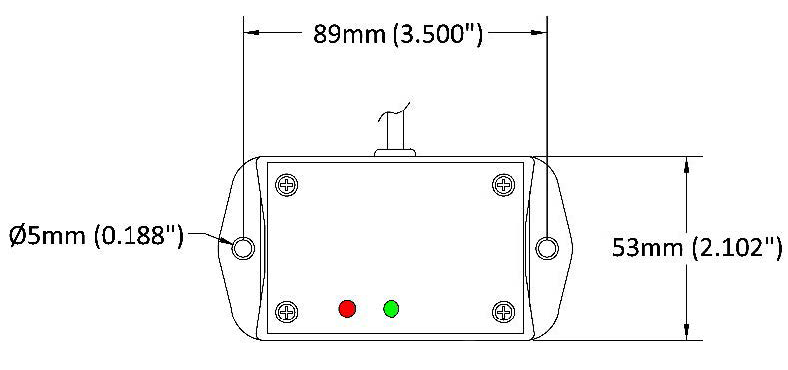
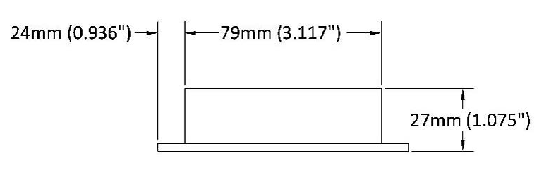
1.3 Physical Specifications
| 住宅 | ABD Plastic |
| 長さ | 53 mm (2.10″) |
| 幅 | 79 mm (3.12″) |
| 高さ | 27 mm (1.08″) |
| ケーブル長 | 45.7 cm (18″) |
| ホールセンター | 89 mm (3.50″) |
| 穴径 | 5 mm (0.19″) |
| 重量 | 150 g |
1.4 RS-232 Settings
| ボーレート | 9600 |
| データ・ビット | 8 |
| パリティ | なし |
| ストップ・ビット | 1 |
1.5 Related Products
| 説明 | 部品番号 | |
| ±45° Range, ±0.1° Repeatability Tilt Switch (Open Collector) | 0729-1757-99 | Buy Now |
| ±45° Range, ±0.1° Repeatability Tilt Switch (Open Collector) | 0729-1758-99 | Buy Now |
Click here to see our entire collection of tilt switches and inclinometers.
2. Installation
2.1 Direction of Measurement
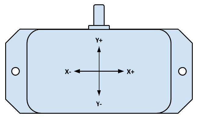
2.2 Mounting
The tilt switch must be mounted horizontally (parallel to the surface of the earth and perpendicular to the force of gravity). For best performance, mount the unit somewhere it will be isolated from vibrations.
2.3 Electrical Connections
| Wire Color | Signal Name | Direction | 説明 |
| レッド | Vcc | Input | Supply Voltage Input: +7 V DC to +35 V DC Regulated |
| ブラック | GND | - | グラウンド |
| オレンジ | - | Input | Zero Set |
| グリーン | C | Input | Relay (Common) |
| バイオレット | NO | 出力 | Relay (Normally Open) |
| ブルー | NC | 出力 | Relay (Normally Closed) |
| ブラウン | Rx | Input | RS-232 Receive |
| イエロー | Tx | 出力 | RS-232送信 |
2.4 Relay Connection
The relay is connected using the C (Common), NO (Normally Open), and NC (Normally Closed) wires. When the switch is in the un-tripped state, NC will form a closed circuit with C, and NO will be an open circuit. When the switch is tripped, NC will become an open circuit, and NO will connect to C. These two states are shown below.
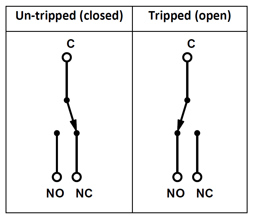
Both outputs can be used to trigger external actions. This is shown in the diagram below.
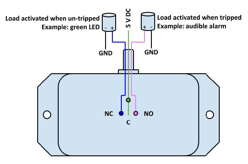
Note that NC and NO only have this behavior with the default polarity of 0. Their behavior will be reversed if the polarity is 1. That is, NC will be open when level and NO will be closed when level. For more information, see 4.4.
3. Set Trip Angle
3.1 Zeroing the Switch
Zero Wire
- If the switch is not mounted at true zero tilt, it may be necessary to zero the switch. Note that the switch can only be zeroed to within ±5° tilt.
- First, ensure the switch is at the zero position and powered off.
- Connect the zero wire (orange) to ground, then power the switch.
- After 3 seconds, remove the wire from ground. Both LEDs should illuminate. The red LED will blink 3 times if the operation was successful.
RS-232
- Ensure the switch is at the zero position and powered on.
- Connect to the switch over RS-232.
- Enter the ‘Z’ (uppercase) command to zero the switch.
3.2 Setting Trip Angle
- The tilt angle can only be adjusted when the switch is in setup mode. Use the ‘set’ command to put the switch in setup mode.
- Select which axis to adjust using the ‘x’ and ‘y’ commands.
- The ‘+’ and ‘-‘ commands can then be used to adjust the trip angle by 0.1°.
- Use the ‘S’ command to save the adjustment.
3.3 Setup Mode Commands
| コマンド | 説明 |
| set | Enter Setup |
| x | Select X Axis |
| y | Select Y Axis |
| + | Increment Trip Angle by 0.1° |
| - | Decrement Trip Angle by 0.1° |
| S | Save Trip Angle |
| ESC | Cancel and Exit Setup |
4. Additional Configuration
4.1 Reset Zero Position
Use the ‘Z’ command to reset the zero position of the tilt switch.
4.2 Trip Delay
Trip delay is how long the switch must pass the trip angle before triggering the relay output to switch.
To set trip delay, use the ‘d’ command. Then, enter 0 to 9 to set the delay. The delay length will be the number you enter times 0.5 seconds.
For example, the following command will set the trip delay to 3.5 seconds:
d7
4.3 Return Delay
Return delay is how long the switch must stay within the trip angle after tripping to switch the relay output.
To set return delay, use the ‘r’ command. Then, enter 0 to 9 to set the delay. The delay length will be the number you enter times 0.5 seconds.
For example, to set the return delay to 2 seconds, use the following command:
r4
4.4 Relay Polarity
Relay polarity determines the outputs of the switch. With a polarity of 1, the NO and NC outputs will be reversed. This is 0 by default.
Relay polarity is set using the ‘p’ command, followed by either ‘0’ or ‘1’ depending on the desired polarity.
For example, the following command will set the polarity to 1:
p1
4.5 Hysteresis
The hysteresis is how far the sensor must return past the trip angle towards level to un-trip. This is done to remove oscillations.
For example, say a sensor has a hysteresis value of 1° and a trip angle of 10°. If the sensor is moved from 0° to 10°, the switch will trip. If the sensor is then moved from 10° to 9.5°, the switch will stay tripped because it is still within the hysteresis value. Moving to 9° would return un-trip the switch.
To set the hysteresis value, use the ‘h’ command, followed by a number 1 to 8. The hysteresis value will the be number entered times 0.25°.
For example, to set the hysteresis to 0.75, use the following command:
h3
4.6 Filter Value
The filter value is an averaging filter used to smooth the tilt before operating on it. The value it is set to determines how many seconds to average measurements together. This is used to filter out vibrations, resulting in a smoother measurement.
For example, say the filter value is 1.072 seconds. Rather than comparing the most recent measurement with the trip angle, it will average all measurements taken in the past 1.072 seconds. This average will then be compared with the trip angle.
To set the filter value, use the ‘f’ command, followed by a number 0 to 9. The filter time will be the number entered times 0.268 seconds.
For example, the following command will set the filter value to 0.536 seconds:
f2
4.7 View Current Configuration
Use the ‘q’ command to get the current configuration of the switch.
4.8 Cancel Command
Before completing any command, you can press ‘ESC’ to cancel the command.
5. Command Reference
| コマンド | 説明 | Inputs |
| ? | Show all commands | |
| set | セットアップモードに入る | |
| x | Select the X axis for setup | |
| y | Select the y axis for setup | |
| + | Increment the selected axis’s trip angle by 0.1° | |
| - | Decrement the selected axis’s trip angle by 0.1° | |
| S | Save new trip angles | |
| Z | Reset zero position of the tilt switch | |
| d | Set trip delay (default 1 second) | 0 to 9 (times 0.5 seconds) |
| r | Set return delay (default 0.5 seconds) | 0 to 9 (times 0.5 seconds) |
| p | Set polarity (default 0) | 0 or 1 |
| h | Set hysteresis value (default 0.25°) | 1 to 8 (times 0.25°) |
| f | Set filter value (default 0 seconds) | 0 to 9 (times 0.268 seconds) |
| q | Show configuration settings | |
| ESC | 現在のコマンドをキャンセルする |